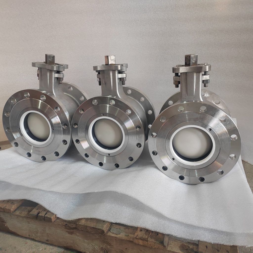

Segment Ball Geometry & Ceramic Trim Tribology
Coupling rotary V-port kinematics with high-hardness ceramic coatings to eliminate seat galling, scaling, and abrasive trim erosion.
1. Why Segment Ball Valves Are Selected for Slurry Service
Segment ball valves (also termed V-port ball valves or eccentric segment valves) offer distinct mechanical and hydrodynamic characteristics tailored to severe slurry and fiber applications.
Segment Ball Geometry & Shearing Mechanism
==========================================
        [ Rotation Angle ]
               \
                \     V-Notch Edge (Shears Fibers)
                 v   /
                +---+
               /  /   \
  Flow ---->  |  |  O  | <-- Spherical Segment Face
               \  \   /
                +---+
                 ^
                 \
                  Flexible / Spring-Loaded Seat Ring
Shearing Action and Wiping Mechanism
The segment ball features a sharp V-shaped contoured edge that closes against a stationary or spring-energized seat ring. As the segment rotates toward closure, the V-notch creates a scissor-like shearing force against the seat edge, cleanly cutting through suspended fibers, rags, and fiber mats. Concurrently, the continuous spherical contact between the segment face and seat ring maintains a wiping action that sweeps away particulate scale and prevents solids from accumulating in the sealing zone.
Flow Path and Capacity Coefficient (Cv)
Unlike globe valves, which force the process fluid through a complex, tortuous path involving two 90° direction changes, segment ball valves feature an unobstructed, straight-through flow architecture. This path minimizes localized fluid turbulence and dynamic pressure drops, yielding significantly higher flow coefficients (Cv) for a given nominal pipe size (NPS). Lower fluid velocities through the valve body reduce particle kinetic energy (Ek = ½mv2), directly decreasing body erosion rates.
Inherent Control Characteristics and Rangeability
The V-port geometry provides a modified equal-percentage control characteristic according to IEC 60534-2-4. This configuration permits precise throttling at low openings (10% to 20% travel) while maintaining high capacity at near-full openings (80% to 90% travel). Typical usable rangeability exceeds 150:1, compared to 30:1 or 50:1 for conventional globe control valves in slurry service.
Torque Profile and Reduced Plugging
The offset shaft design unseats the segment with minimal initial rotation, reducing seat friction and wear during throttling. The absence of internal cavities where solids can settle minimizes plugging risks, maintaining low, predictable operating torque requirements over extended operating cycles.
2. Engineering Advantages of Ceramic-Coated Trim
While segment ball architecture resolves structural flow and shearing challenges, standard metallic or hard-faced materials remain susceptible to surface degradation under severe abrasive and corrosive conditions. Applying engineered ceramic coatings or structural ceramic liners directly addresses these material limitations.
      Hardness (Vickers HV) vs. Wear Mechanism
      ========================================
 2500 HV +-------------------------------------+ Ceramic Coatings
         |                                     | (ZrO2, Al2O3, Cr2O3)
 2000 HV |                                     |
         |                                     |
 1500 HV |-------------------------------------|
         |                                     | Quartz / Sand (SiO2)
 1000 HV |-------------------------------------| Titanium Dioxide (TiO2)
         |                                     | Stellite / Hard-facing
  500 HV |-------------------------------------| 316L / Duplex Metal
        0 HV +-------------------------------------+
Surface Hardness and Abrasion Resistance
Engineered ceramics such as Partially Stabilized Zirconia (ZrO2), Alpha Alumina (Al2O3), Silicon Carbide (SiC), or High-Velocity Oxygen-Fuel (HVOF) applied Chromium Oxide (Cr2O3) exhibit hardness values ranging from 1100 HV to over 2000 HV (Vickers scale). Because these values exceed the micro-hardness of common paper mill abrasives—including sand (SiO2 ≈ 1000–1200 HV) and TiO2 (≈ 800–1000 HV)—the Hp / Hm ratio remains well below the critical threshold of 1.0. Micro-cutting wear is virtually eliminated, preserving sealing boundary geometry over years of operation.
Low Coefficient of Friction and Control Loop Stability
Polished ceramic surfaces achieve surface roughness values down to Ra ≤ 0.1 μm. The dynamic friction coefficient (μ) of ceramic-on-ceramic or ceramic-on-PTFE/PEEK interfaces under slurry lubricated conditions drops below 0.10 (compared to μ = 0.30–0.50 for stainless steel pairs). Lower friction yields specific process control benefits:
- Minimized Deadband and Hysteresis: Reduces stick-slip phenomena at fine movement increments, enabling precise positioner response (≤ 0.5% input signal change) per IEC 60534-6.
- Lower Actuator Thrust/Torque Requirements: Reduces required actuator sizing safety factors, allowing smaller pneumatic actuators with faster dynamic response times.
Chemical Inertness across the pH Spectrum
Engineered ceramics consist of fully oxidized or covalently bonded compounds exhibiting high thermodynamic stability. They remain chemically inert across pH 0 to 14, providing resistance to strong organic/inorganic acids, oxidizers, and concentrated caustic solutions. Galvanic corrosion between the ball trim and seat ring is fully eliminated.
Scale Adhesion Suppression
The low surface energy and ultra-smooth surface finish (Ra ≤ 0.1 μm) of ceramic materials inhibit crystal nucleation. Green liquor scale (CaCO3, Na2SO4) and organic pitch fail to establish mechanical anchoring on the smooth ceramic surface. Wiping action during normal actuation breaks off weak surface deposits, maintaining low operating torque and preventing mechanical lockup.
3. Engineering Trim Material Comparison
Evaluating trim selection requires balancing tribological metrics, corrosion resistance, dynamic response, and mechanical limits.
| Engineering Parameter | Standard Metallic Trim (316L / Duplex 2205) |
Hard-Faced Metallic Trim (Stellite 6 / Chrome Carbide) |
Ceramic-Coated / Structural Ceramic Trim |
|---|---|---|---|
| Microhardness Range | 200 – 320 HV | 500 – 700 HV | 1100 – 2200 HV |
| Abrasive Wear Resistance (SiO2, TiO2) | Poor (Hp/Hm >> 1.2) | Moderate (Hp/Hm ≈ 1.2) | Superior (Hp/Hm < 0.6) |
| Erosion-Corrosion Synergy Resistance | Low (Passive film easily removed) | Moderate (Cobalt/Nickel binder leaching) | High (Chemically inert matrix) |
| Dynamic Friction Coeff. (μ, Slurry) | 0.35 – 0.50 | 0.25 – 0.40 | 0.08 – 0.15 |
| Control Deadband / Hysteresis | High (> 3%, due to stick-slip) | Moderate (1.5% – 3%) | Low (< 0.5%) |
| Thermal Shock Resistance | Excellent (ΔT > 300°C) | Good (ΔT ≈ 200°C) | Moderate to Low (ΔT control required) |
| Fracture Toughness (KIC) | Very High (> 50 MPa·m1/2) | High (30 – 40 MPa·m1/2) | Moderate (5 – 12 MPa·m1/2) |
| Scale / Pitch Adhesion | High | High | Very Low |
| Relative Capital Cost (Trim) | Baseline (1.0×) | 1.5× – 2.0× | 2.5× – 4.0× |
| Mean Time Between Failures (Severe Slurry) | 2 to 6 months | 6 to 12 months | 36 to 60+ months |