
RELEBEL Solutions
Redundant Valve Manifold (RVM) Solutions
Redundant Valve Manifolds for Critical Shutdown Applications
The performance of a shutdown valve assembly depends not only on the actuator or solenoid valve, but on how the complete control package is engineered. An integrated manifold architecture establishes a standardized interface for pressure control, maintenance, inspection, and long-term lifecycle management of critical shutdown systems.
A Redundant Valve Manifold (RVM) replaces complex field-built tubing arrangements with a factory-engineered control assembly that improves installation consistency, reduces potential leak paths, simplifies maintenance, and provides a repeatable platform for application-specific shutdown architectures.
Whether applied to process shutdown valves or Safety Instrumented Functions, an integrated RVM establishes a standardized engineering foundation for reliable operation, maintainability, and future lifecycle support.
Why Integrated RVM Architecture?
Conventional shutdown valve assemblies are typically constructed from individually mounted solenoid valves, regulators, fittings, and external tubing. While this approach offers installation flexibility, it can also increase engineering variability, maintenance effort, inspection complexity, and the number of potential leak paths throughout the operational lifecycle.
A Redundant Valve Manifold (RVM) consolidates these functions into a factory-engineered control assembly with standardized internal flow paths and repeatable component integration. The result is a shutdown package that improves engineering consistency while simplifying installation, servicing, and long-term lifecycle management.
| Conventional Field-Built Assembly | Integrated RVM Architecture |
|---|---|
| Individually mounted control components | Factory-engineered integrated assembly |
| Extensive external tubing and fittings | Integrated internal flow passages with fewer external connections |
| Greater potential leak paths and installation variability | Standardized assembly with improved engineering consistency |
| Site-dependent configuration and documentation | Repeatable architecture with consistent package integration |
| Longer inspection, maintenance, and component replacement activities | Simplified servicing with improved maintenance accessibility throughout the equipment lifecycle |
Rather than focusing only on individual components, integrated RVMs establish a standardized shutdown architecture that improves consistency from installation through maintenance. Different manifold designs further optimize maintainability, redundancy, and operational flexibility according to the functional requirements of the shutdown system.
RVM Configurations and Shutdown Architecture Compatibility
Selecting an appropriate Redundant Valve Manifold (RVM) involves more than choosing a physical assembly. The manifold configuration should support the required maintenance strategy while remaining compatible with the shutdown voting philosophy defined for the Safety Instrumented Function (SIF). Engineering decisions therefore consider maintainability, proof testing, operational availability, and process safety as an integrated design objective.
Compact, Semi-Modular, and Modular RVMs provide different levels of accessibility and serviceability. Combined with the appropriate shutdown architecture, they create a standardized control package capable of supporting a wide range of emergency shutdown applications.
Engineering Selection Matrix
| RVM Configuration | Maintenance Philosophy | Typical Shutdown Architecture | Typical Applications |
|---|---|---|---|
| Compact | Simple integrated assembly | 1oo2 | Standard ESD valves |
| Semi-Modular | Improved inspection and proof testing | 1oo2 / 2oo2 | Critical process isolation |
| Modular | Online maintenance and maximum serviceability | 2oo2 / 2oo3 | High-availability SIS and critical shutdown systems |
Compact Configuration
Designed for applications requiring a simple and standardized shutdown package with minimal installation footprint. Integrated fluid routing reduces external tubing while simplifying commissioning and routine maintenance.
Semi-Modular Configuration
Provides improved accessibility for inspection, pressure monitoring, and proof testing. The modular arrangement simplifies diagnostics while maintaining a compact engineering solution for critical process shutdown applications.
Modular Configuration
Intended for shutdown systems where operational continuity is essential. Individual functional modules can be isolated or serviced with minimal disruption, supporting advanced maintenance strategies and high system availability.
Engineering Considerations
Selecting an RVM should begin with the required Safety Instrumented Function (SIF) and the desired balance between process safety, operational availability, and maintainability. While Compact, Semi-Modular, and Modular configurations define the physical arrangement of the manifold, the shutdown voting philosophy (such as 1oo2, 2oo2, or 2oo3) determines how the system responds to process demands. Evaluating these parameters together enables a standardized, maintainable, and application-specific shutdown solution rather than a one-size-fits-all manifold assembly.
Integrated Shutdown Control Functions
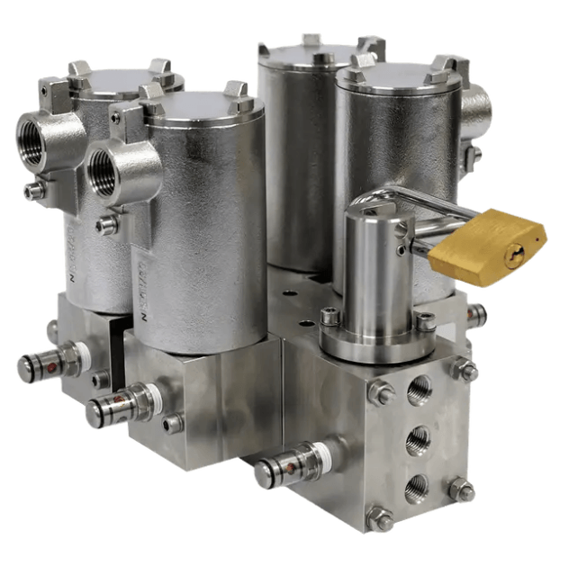
An RVM is more than a manifold assembly. It provides a standardized platform that integrates the control, monitoring, testing, and maintenance functions required for reliable shutdown valve operation. By consolidating these engineering functions into a single package, field installation is simplified while inspection, proof testing, and long-term lifecycle support become more consistent and efficient.
Rather than selecting individual components independently, engineers can define an integrated shutdown package that supports the complete operational lifecycle—from shutdown demand to routine maintenance.
Shutdown Lifecycle Integration
1. Control & Actuation
Engineering Objective
Ensure reliable execution of shutdown commands by integrating the primary control elements into a standardized and fail-safe control package.
Integrated Functions
- Redundant solenoid valve arrangements
- Pilot valve integration
- Manual override capability
- Fail-safe actuation control
2. Pressure Management
Engineering Objective
Maintain stable operating pressure while providing accurate pressure control and condition monitoring for dependable actuator performance.
Integrated Functions
- Pressure regulators
- Pressure gauges
- Pressure transmitters
- Flow and pressure monitoring
3. Monitoring & Diagnostics
Engineering Objective
Provide operational visibility and simplify fault identification through integrated monitoring and diagnostic interfaces.
Integrated Functions
- Pressure indication
- Pressure transmitters
- Minimess® test points
- Proximity switches
- Diagnostic ports
4. Proof Testing
Engineering Objective
Support routine verification of shutdown functionality while minimizing process interruption and reducing proof-test duration.
Integrated Functions
- Partial Stroke Testing (PST)
- Pressure verification points
- Functional test connections
- Integrated test interfaces
5. Maintenance & Lifecycle Support
Engineering Objective
Reduce maintenance effort, improve accessibility, and simplify servicing throughout the operational lifecycle of the shutdown package.
Integrated Functions
- Isolation and bypass arrangements
- Online maintenance capability
- Modular component replacement
- Improved maintenance accessibility
Engineering Perspective
An integrated RVM combines multiple shutdown control functions into a single engineered package, reducing installation variability while improving maintainability, proof testing, and operational reliability. Instead of optimizing individual components, this approach standardizes the complete shutdown control architecture, providing a scalable foundation for Safety Instrumented Systems (SIS) across a wide range of industrial applications.
Shutdown Control Technology Platforms
The operating medium plays a fundamental role in shutdown system performance. Selecting the appropriate technology platform depends not only on actuator size or available utilities, but also on safety requirements, environmental conditions, maintenance strategy, and the expected operational lifecycle of the installation.
Whether utilizing pneumatic, hydraulic, or gas-over-oil control systems, the objective remains the same: delivering reliable, repeatable, and fail-safe valve operation while supporting efficient maintenance and long-term asset reliability.
Technology Selection Criteria
Before selecting a shutdown control technology, engineers typically evaluate several project-specific parameters that directly influence system performance and maintainability.
Pneumatic Control Systems
Engineering Focus
Utilizes clean instrument air to provide fast, reliable valve actuation with a simple and proven shutdown architecture suitable for most industrial process facilities.
Typical Applications
- General ESD systems
- Process plants
- Chemical & Petrochemical
- Refineries
- Utility shutdown valves
Hydraulic Control Systems
Engineering Focus
Designed for applications requiring high operating force, precise control, and dependable shutdown performance where large actuators or demanding service conditions exceed pneumatic capabilities.
Typical Applications
- Large quarter-turn valves
- Steam turbines
- Offshore platforms
- High-integrity shutdown systems
- Critical isolation service
Gas-over-Oil Control Systems
Engineering Focus
Combines the reliability of stored gas energy with hydraulic power transmission, making it particularly suitable for remote installations where instrument air or hydraulic power units are unavailable.
Typical Applications
- Pipeline isolation valves
- Remote block valve stations
- Line Break Systems (LBS)
- Cross-country pipelines
- Unmanned installations
Engineering Comparison
| Technology | Power Source | Typical Application | Primary Advantage |
|---|---|---|---|
| Pneumatic | Instrument Air | General Process Shutdown | Simple, fast response |
| Hydraulic | Hydraulic Pressure | High-Torque Isolation | High operating force |
| Gas-over-Oil | Stored Gas & Hydraulic Oil | Remote Pipeline Shutdown | Independent operation |
Engineering Perspective
Selecting the appropriate shutdown control technology is an engineering decision based on process conditions, available utilities, required actuator performance, environmental constraints, and lifecycle objectives. Matching the technology platform to the application improves system reliability, simplifies maintenance, and ensures the shutdown package performs as intended throughout its service life.
Industrial Applications & Typical Use Cases
Redundant Valve Manifolds are applied wherever shutdown valve reliability, operational availability, and maintainability are critical to plant safety. Although the engineering principles remain consistent, each application presents different operational priorities that influence the required control architecture, technology platform, and integrated shutdown functions.
Selecting an RVM therefore begins with understanding the shutdown duty rather than simply choosing a manifold configuration.
Emergency Shutdown (ESD)
Designed to provide rapid and dependable valve closure following an emergency shutdown demand while supporting proof testing and simplified maintenance throughout the equipment lifecycle.
Typical Engineering Priorities
- Fast shutdown response
- High operational reliability
- Routine proof testing
- Reduced maintenance downtime
Safety Instrumented Systems (SIS)
Integrated shutdown packages supporting Safety Instrumented Functions where shutdown architecture, diagnostics, and maintenance strategy contribute to achieving the required functional safety objectives.
Typical Engineering Priorities
- Voting architectures
- Diagnostic capability
- Proof-test efficiency
- Lifecycle management
Pipeline Isolation
Remote pipeline block valves often require autonomous shutdown capability where stored-energy actuation and high system availability are essential for protecting long-distance transmission assets.
Typical Engineering Priorities
- Gas-over-oil systems
- Remote operation
- Stored energy actuation
- Line Break applications
Critical Process Isolation
Applied where large process valves require dependable actuation, simplified maintenance, and high operational availability throughout continuous plant operation.
Typical Engineering Priorities
- Hydraulic actuation
- High operating force
- Online maintenance
- Modular architectures
HIPPS & High-Integrity Protection
High-integrity shutdown applications demand reliable actuation, fault tolerance, and maintainable shutdown architectures capable of supporting critical overpressure protection strategies.
Typical Engineering Priorities
- High availability
- Fault tolerance
- Integrated diagnostics
- Reliable shutdown execution
Turbines & Rotating Equipment
Steam turbines, compressors, and other critical rotating equipment require dependable hydraulic shutdown systems capable of rapid response and repeatable performance under demanding operating conditions.
Typical Engineering Priorities
- Hydraulic control
- High response reliability
- Pressure monitoring
- Maintenance accessibility
Engineering Perspective
The most effective shutdown solution is achieved by aligning the application requirements with the appropriate RVM configuration, shutdown architecture, integrated control functions, and operating technology. Evaluating these engineering parameters together results in a standardized, maintainable, and application-specific shutdown package that supports safe and reliable operation throughout the asset lifecycle.
Engineering Selection Guide
Selecting a Redundant Valve Manifold involves more than choosing a manifold configuration or operating medium. The final solution should balance process safety, actuator performance, utility availability, maintenance philosophy, and lifecycle objectives. The matrix below summarizes typical engineering considerations that help identify the most appropriate shutdown package architecture.
Engineering Decision Matrix
| Engineering Priority | Recommended Configuration | Preferred Technology | Typical Application |
|---|---|---|---|
| Standard emergency shutdown | Compact | Pneumatic | General ESD valves |
| Simplified maintenance | Semi-Modular | Pneumatic or Hydraulic | Process isolation |
| Maximum operational availability | Modular | Hydraulic | Critical shutdown valves |
| Remote autonomous operation | Modular | Gas-over-Oil | Pipeline block valves |
| High actuator torque | Modular | Hydraulic | Large ball, butterfly and plug valves |
Before Final Selection
- Available utility source
- Required actuator torque
- Required shutdown time
- Environmental conditions
- Installation constraints
Lifecycle Considerations
- Online maintenance requirements
- Proof testing strategy
- Diagnostic capability
- Future system upgrades
- Long-term maintainability
Engineering Summary
The most effective Redundant Valve Manifold solution is achieved by evaluating the complete shutdown system rather than selecting individual components in isolation. Configuration, control functions, operating technology, and maintenance strategy should be considered together to deliver a shutdown package that is reliable, maintainable, and aligned with the application’s functional and operational requirements.
Need Help Selecting the Right Shutdown Architecture?
Every shutdown application has unique operational, safety, and maintenance requirements. Selecting the appropriate Redundant Valve Manifold involves more than choosing components—it requires balancing shutdown philosophy, control architecture, operating technology, and lifecycle considerations.
Our engineering team supports EPC contractors, system integrators, OEMs, and end users in specifying integrated shutdown packages tailored to their application, performance objectives, and maintenance strategy.
How We Can Support
- RVM configuration selection
- Shutdown architecture evaluation
- Technology platform recommendation
- Component integration
- Application-specific engineering support
- Technical proposal & RFQ assistance