
Innovative Solutions
ICO4S Solenoid Valve for High-Integrity Shutdown and Safety Systems
IMI Maxseal ICO4S High-Capacity Solenoid Valve Platform for Pneumatic & Hydraulic Control Systems
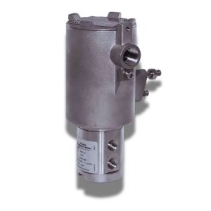
The IMI Maxseal ICO4S is a high-capacity direct-acting solenoid valve platform engineered for demanding pneumatic and hydraulic control applications. Designed to support larger actuator packages, higher flow requirements, and elevated operating pressures, it provides flexible configuration options for valve automation, emergency shutdown (ESD), process isolation, and industrial fluid power systems.
Available in multiple valve functions, mounting arrangements, connection types, port sizes, voltage options, and hazardous-area configurations, the ICO4S platform enables engineers to configure a solution that matches specific actuator, process, and installation requirements rather than adapting the application to a fixed valve design.
Engineering Focus: This page examines the ICO4S platform from an engineering perspective, including available configurations, performance characteristics, system integration, application suitability, and practical selection considerations for high-demand pneumatic and hydraulic control systems.
Engineering Configurations
The IMI Maxseal ICO4S platform is available in multiple engineering configurations to support different actuator architectures, operating media, installation methods, and project specifications. Selecting the appropriate configuration should be based on system requirements rather than component availability alone.
| Configuration Category | Available Options | Typical Engineering Application |
|---|---|---|
| Valve Function | 2/2 • 3/2 • 5/2 | Isolation, spring-return actuators, double-acting actuators and directional control. |
| Operating Medium | Instrument Air • Nitrogen • Hydraulic Oil (variant dependent) | Valve automation, pneumatic control systems and hydraulic power applications. |
| Mounting Configuration | NAMUR • Inline • Manifold | Direct actuator mounting, remote installation or multi-valve assemblies. |
| Port Connections | NPT • G (BSPP) • Manifold Interface | Compatible with common industrial piping standards and packaged systems. |
| Port Sizes | 1/4″ • 3/8″ • 1/2″ • 3/4″ | Selected according to actuator air demand, hydraulic flow requirements and system capacity. |
| Coil Voltages | 24 VDC • 48 VDC • 110 VAC • 230 VAC | Integration with PLC, DCS, SIS and plant electrical systems. |
| Hazardous-Area Protection | Ex d • Ex ia | Suitable for hazardous process environments where certified protection is required. |
| Manual Override | Push Button • Twist & Lock • Locking Override | Supports commissioning, maintenance and functional testing activities. |
| Construction | 316L Stainless Steel | Corrosive environments, offshore installations and demanding industrial services. |
Engineering Note: Not every configuration is available in every valve function, operating medium, pressure class, or certification option. Final selection should always be verified against the applicable IMI Maxseal ICO4S technical documentation and project specifications.
Engineering Matrix: IMI Maxseal ICO3S vs. ICO4S
Direct comparison of mechanical boundaries, flow capacities, and safety parameters for specification inside IEC 61508 safety instrumented systems.
| Technical Parameter | IMI Maxseal ICO3S | IMI Maxseal ICO4S |
|---|---|---|
| Functional Loop Allocation | Pneumatic pilot lines, compact ESD panels, low-volume SIF loops. | High-pressure pneumatic and high-volume hydraulic final element actuation lines. |
| Mechanical Trim Architecture | Direct-acting, balanced spool configuration. | Direct-acting, force-assisted poppet design. |
| Maximum Operating Pressure Differential (MOPD) | Pneumatic: 0 to 12 bar (options up to 16 bar based on coil choice). | Pneumatic: 0 to 20 bar. Hydraulic: 0 to 414 bar. |
| Fluid Media Compatibility | Instrument air, inert gases, dry sweet gas. | Pneumatic media, mineral oils, synthetic hydraulic fluids (up to 400 cSt). |
| Flow Capacity (Cv / Kv) | Up to Cv 0.6 (Kv 0.5) via 1/4″ NPT ports. | Up to Cv 0.8 (Kv 0.7) via 1/4″ to 1/2″ NPT ports. |
| Seat Leakage Integrity | ANSI/FCI 70-2 Class IV / Class V elastomer sealing. | ANSI/FCI 70-2 Class VI bubble-tight (Viton or metal-to-metal). |
| Target Actuator Swept Volume | Linear or quarter-turn displacements < 5 liters total volume. | High-displacement scotch-yoke or rack-and-pinion units > 5 liters total volume. |
| Process Infrastructure Allocation | Downstream plant processing blocks, utility air systems, onshore refining. | Offshore topsides, subsea chemical injection manifolds, LNG liquefaction trains. |
| Metallurgical Composition | 316L Stainless Steel standard housing block. | 316L Stainless Steel compliant with NACE MR0175/ISO 15156 sour service trim requirements. |
| Functional Safety Compliance | IEC 61508 third-party certified SIL 3 capable (HFT=0); ATEX/IECEx Zone 1. | IEC 61508 third-party certified SIL 3 capable (HFT=0); ATEX/IECEx Zone 1. |
Sizing validation requires matching exact fluid viscosity profiles to target process safety time (PST) parameters. Contact NordenFlow for certified Cv calculations and safety data sheet (SDS) integration loops.
Engineering Specifications & Performance Characteristics
The engineering value of the IMI Maxseal ICO4S extends beyond published specifications. Flow capacity, operating pressure, switching characteristics, electrical performance, and construction materials collectively determine how the valve performs within demanding pneumatic and hydraulic control systems.
Flow Capacity & Cv Performance
Higher flow capacity allows the valve to supply and exhaust larger actuator volumes efficiently. Correct Cv selection should always consider actuator size, tubing arrangement, pressure losses and required stroke time rather than valve size alone.
Operating Pressure Envelope
Available pressure ratings allow the ICO4S platform to support demanding pneumatic and selected hydraulic applications. The appropriate configuration should be matched to both normal operating pressure and maximum design pressure.
Dynamic Switching Performance
Actual response time depends on the complete control circuit. Valve performance is influenced by actuator volume, supply pressure, exhaust restrictions, tubing length and downstream components as well as the valve itself.
Electrical Characteristics
Multiple voltage options support integration with PLC, DCS and SIS installations. Coil selection should consider supply stability, duty cycle, power consumption and ambient operating temperature.
316L Stainless Steel Construction
A 316L stainless steel body provides corrosion resistance for offshore, chemical, LNG and other aggressive industrial environments while supporting long-term mechanical durability.
Hazardous-Area & Environmental Protection
Available hazardous-area certifications together with environmental protection options allow the ICO4S platform to be specified for demanding industrial installations where environmental exposure and regulatory compliance are critical engineering considerations.
Engineering Insight: Published specifications should not be assessed independently. Flow capacity, operating pressure, electrical characteristics, installation layout and actuator dynamics interact as a complete control system, and each should be evaluated together during specification and package design.
Selecting Between Pneumatic and Hydraulic ICO4S Configurations
The ICO4S platform supports both pneumatic and hydraulic control applications through dedicated valve configurations. Selecting the appropriate version depends on the operating medium, actuator characteristics, pressure requirements, and overall control philosophy of the automation system.
| Engineering Consideration | Pneumatic Configuration | Hydraulic Configuration |
|---|---|---|
| Operating Medium | Instrument Air or Nitrogen | Hydraulic Oil |
| Typical Actuator | Pneumatic Spring-Return or Double-Acting | Hydraulic Linear or Quarter-Turn |
| Primary Design Priority | Airflow Capacity and Response Time | Pressure Capability and Hydraulic Control |
| Typical Installation | Valve Automation Systems, ESD Packages, Process Isolation | Hydraulic Power Units, High-Force Valve Actuation, Process Control |
| Engineering Review | Review actuator air demand, Cv, tubing layout and supply pressure. | Review hydraulic pressure, fluid compatibility, flow requirement and sealing materials. |
Engineering Note: The availability of pneumatic and hydraulic versions depends on the selected ICO4S model. Final configuration should always be verified against the applicable IMI Maxseal technical documentation to ensure compatibility with the operating medium, pressure class, and project specification.
Engineering Insights Beyond the Datasheet
Published specifications define the operating limits of a solenoid valve, but they rarely explain how the valve behaves once integrated into a complete automation package. The following observations are based on practical engineering considerations commonly encountered during valve automation projects, commissioning, and plant modifications.
Higher Cv Does Not Always Produce Faster Stroke Times
Increasing valve capacity improves performance only when the solenoid valve is the actual flow restriction. In many installations the limiting factor is actuator volume, tubing diameter, exhaust restriction or available supply pressure.
Hydraulic Systems Demand Different Engineering Priorities
Hydraulic configurations should not be evaluated using the same assumptions applied to pneumatic systems. Pressure capability, fluid cleanliness, seal compatibility and return-line design often influence long-term reliability more than valve capacity.
A Larger Solenoid Valve Cannot Compensate for Poor Package Design
Replacing a valve with a higher-flow model rarely resolves issues caused by undersized tubing, contaminated air, inadequate hydraulic supply, or improperly selected actuators. The complete control package should always be reviewed before changing components.
Power Consumption Influences More Than Electrical Load
Coil wattage affects enclosure temperature, cabinet heat dissipation and long-term component life. In continuously energized applications, selecting the appropriate coil can improve operational stability while reducing unnecessary power consumption.
Standardization Simplifies Lifecycle Support
Using a configurable valve platform across multiple projects can reduce spare-part inventories, simplify engineering documentation and improve maintenance consistency throughout the facility.
Successful Valve Automation Is a System Decision
The performance of a solenoid valve depends on its interaction with actuators, air or hydraulic supply, tubing, manifolds, accessories and the control philosophy. Evaluating these elements together generally delivers better results than optimizing any individual component.
ICO4S Model Code Structure
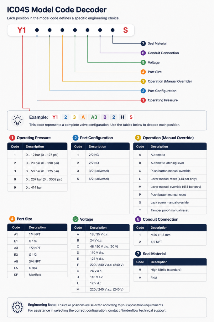
Every ICO4S model number is generated from a structured engineering coding system. Each character represents a specific configuration parameter, including operating pressure, valve function, manual override, port size, voltage, conduit connection, and seal material. Understanding this structure simplifies specification reviews, replacement verification, and new valve selection without relying solely on the product catalogue.
Engineering Example: Decoding an ICO4S Model Number
The example below illustrates how a complete ICO4S model code is interpreted. Reading the code from left to right allows each engineering selection to be identified before reviewing the detailed option tables.
| Prefix | Pressure | Function | Operation | Port Size | Voltage | Conduit | Seal |
|---|---|---|---|---|---|---|---|
| Y1 | 1 | 3 | A | A3 | B | 2 | H |
| Fixed Prefix | 0–12 bar | 3/2 Universal | Automatic | 1/2″ NPT | 24 VDC | 1/2″ NPT | High Nitrile |
Engineering Interpretation: This example represents an ICO4S configured for a 0–12 bar operating range with a 3/2 universal valve function, automatic operation, 1/2″ NPT ports, a 24 VDC coil, 1/2″ NPT conduit entry, and High Nitrile seals.
Engineering Note: The diagram introduces the configuration sequence only. Detailed code options for each position are provided in the engineering tables below, allowing individual model numbers to be decoded or configured step by step.
Is the Solenoid Valve Really the Limiting Factor?
Increasing valve size or selecting a higher-capacity model does not always improve system performance. In many valve automation projects, actuator characteristics, supply conditions, installation layout, or control philosophy have a greater influence on response than the solenoid valve itself.
An engineering discussion typically begins by reviewing:
- The existing valve automation package and actuator arrangement
- The operating medium (instrument air, nitrogen, or hydraulic oil)
- Required operating pressure and response objectives
- The current solenoid valve configuration and installation method
- Project constraints, modernization objectives, or reliability concerns
Nordenflow Engineering Philosophy
Improving system performance does not always require replacing components. Understanding how the valve, actuator, control philosophy, and installation interact often identifies opportunities to improve reliability using the most appropriate technology.