
RELEBEL Solutions
Industrial Solenoid Valves for Automation Systems
Industrial Solenoid Valves for Valve Automation Systems
Industrial solenoid valves provide the switching interface between electrical control systems and the directional control of pneumatic or hydraulic power. They initiate actuator movement, route compressed air or hydraulic fluid, and influence switching repeatability, response characteristics, and overall reliability within automated valve assemblies used throughout industrial process and safety applications.
Selecting the appropriate solenoid valve extends beyond matching voltage, port size, or mounting style. Directional valve architecture, pilot arrangement, flow coefficient (Cv), operating pressure, environmental conditions, media compatibility, and actuator characteristics all contribute to predictable system performance under both normal operating and demand conditions. In hydraulic automation systems, these considerations also influence hydraulic directional valves, pressure control circuits, and integrated manifold assemblies.
This page explores the engineering principles behind industrial solenoid valve technology, switching behaviour, hazardous-area suitability, and integration within pneumatic and hydraulic valve automation systems. Product-specific information for the Maxseal ICO3S and ICO4S families is available on their dedicated product pages.
Engineering Conditions That Influence Solenoid Valve Performance
Solenoid valve performance depends on the operating conditions surrounding the valve rather than the component alone. Available pressure, actuator characteristics, switching requirements, installation environment, fluid properties, and mechanical integration establish the engineering constraints that determine valve selection and long-term operating performance.
Electrical Signal Conversion
The solenoid valve forms the interface between the control system and the pneumatic or hydraulic control circuit. Switching consistency depends on how accurately electrical commands are converted into controlled fluid routing within the valve automation system.
Available Operating Pressure
Supply pressure and pressure differential determine whether direct-acting or pilot-operated valve designs are appropriate. In hydraulic systems, operating pressure and fluid characteristics also influence spool movement, pressure stability, and switching performance.
Actuator Demand
Actuator volume, required response time, available Cv, and system flow requirements determine how efficiently compressed air or hydraulic fluid is delivered and exhausted during actuator movement.
Installation Environment
Ambient temperature, vibration, moisture, corrosion, and hazardous-area classification influence enclosure selection, sealing materials, electrical protection, and long-term operational reliability.
Mechanical Integration
Mounting arrangement, tubing or hydraulic piping layout, exhaust routing, manifold design, and actuator interface affect installation complexity, maintenance accessibility, switching efficiency, and overall system reliability.
System Modernization
Existing valve automation assemblies can often achieve improved switching performance by reviewing valve architecture, hydraulic or pneumatic circuit design, and operating conditions before replacing the complete actuator package.
Solenoid Valve Operating Principles
Solenoid valve architecture determines how electrical energy is converted into the directional control of pneumatic or hydraulic power. Selecting the appropriate operating principle depends on available supply pressure, actuator configuration, switching philosophy, and installation requirements. Understanding these differences helps ensure the valve architecture matches the intended operating conditions before detailed component selection begins.
Direct-Acting Solenoid Valves
The solenoid coil moves the valve element directly without relying on system pressure. This operating principle is suitable where little or no pressure differential is available and provides predictable switching for applications requiring reliable operation under varying pneumatic or hydraulic pressure conditions.
Pilot-Operated Solenoid Valves
Pilot-operated designs use system pressure to assist valve movement, allowing higher flow capacity with lower electrical power consumption. Reliable operation depends on maintaining sufficient operating pressure and is widely applied in both pneumatic valve automation and hydraulic directional control systems.
Internal and External Pilot Arrangements
Internal pilot valves use available system pressure to operate the pilot stage, whereas external pilot designs receive pilot pressure from an independent source. External pilot arrangements are commonly selected when operating pressure varies or cannot reliably actuate the pilot mechanism.
Monostable Configurations
Monostable valves return automatically to their normal position when electrical power is removed. They are commonly applied where a predefined fail position is required following loss of control power in pneumatic and hydraulic automation systems.
Bistable Configurations
Bistable valves remain in their last switching position until a subsequent electrical command changes the valve state. This operating principle is suitable where position retention is required without continuous coil energization, particularly in applications where maintaining the last commanded state is desirable.
Engineering Consideration
Operating principle should be established before evaluating flow coefficient, hazardous-area certification, electrical characteristics, or product family. Matching the valve architecture to the application establishes the foundation for reliable integration with pneumatic actuators, hydraulic directional valves, and complete valve automation systems.
Typical Industrial Applications
Industrial solenoid valves are applied wherever electrical control signals must initiate, interrupt, or redirect pneumatic or hydraulic power. Although the electromagnetic operating principle remains the same, valve configuration, mounting method, and performance requirements vary according to the actuator package, control philosophy, and operating duty.
On-Off Valve Automation
Solenoid valves control spring-return and double-acting pneumatic actuators as well as hydraulic actuators used on ball, butterfly, plug, and gate valves where dependable switching between open and closed positions is required.
Automated Valve Assemblies
Integrated automation packages combine solenoid valves with position switches, positioners, air preparation equipment, hydraulic manifold assemblies, and related accessories to create compact, maintainable valve automation solutions.
Emergency Shutdown Valves
Emergency Shutdown Valve (ESDV) assemblies use solenoid valves to initiate pneumatic or hydraulic actuator movement following a shutdown command. This architecture is widely applied in process safety systems where dependable valve actuation is essential, while functional safety philosophy is addressed separately within dedicated Safety Instrumented System (SIS) engineering pages.
Process Automation Equipment
Pneumatic and hydraulic directional control valves are widely used on package equipment, utility systems, OEM machinery, and automated process units where reliable actuator control is required throughout normal operating cycles.
Hazardous Area Installations
Oil & gas, LNG, chemical processing, power generation, offshore, and other hazardous environments require valve automation systems that incorporate appropriately certified solenoid valves for pneumatic or hydraulic service, according to the installation classification.
Retrofit and Modernization Projects
Existing valve automation assemblies can often achieve improved performance by replacing or reconfiguring the solenoid valve, hydraulic directional valve, or manifold arrangement while retaining the actuator and valve assembly, reducing project scope and installation downtime.
Pneumatic Solenoid Valve Selection
Pneumatic solenoid valve selection is primarily determined by actuator configuration, valve function, and installation method. The comparison below summarizes the most common configurations used in industrial pneumatic valve automation systems.
| Configuration | Typical Application | Advantages | Engineering Considerations |
|---|---|---|---|
| 2/2 Valve | On/off media isolation | Simple shut-off function | Not intended for directional actuator control |
| 3/2 Valve | Spring-return pneumatic actuators | Controls supply and exhaust through a single actuator port | Preferred where fail-safe actuator operation is required |
| 5/2 Valve | Double-acting pneumatic actuators | Independent control of both actuator chambers | Requires two actuator connections |
| NAMUR Mounting | Direct actuator installation | Compact assembly with minimal tubing | Requires a compatible actuator interface |
| Inline Mounting | Remote valve installation | Flexible installation location | Additional tubing increases installation complexity |
| Manifold Mounting | Multiple valve assemblies | Shared air supply and simplified maintenance | Installation arrangement only, not a redundant valve architecture |
Hydraulic Directional Control Valve Selection
Hydraulic directional control valves are selected according to circuit architecture, spool configuration, operating pressure, flow requirements, and mounting method. Unlike pneumatic solenoid valves, hydraulic valve selection is strongly influenced by hydraulic circuit design and system operating characteristics.
| Configuration | Typical Application | Advantages | Engineering Considerations |
|---|---|---|---|
| 4/2 Valve | Simple hydraulic directional control circuits | Straightforward directional switching with compact design | Best suited where a neutral center position is not required |
| 4/3 Valve | Double-acting hydraulic actuators | Multiple center position options for different circuit functions | Center spool configuration must match the hydraulic circuit design |
| CETOP Mounted | Hydraulic power units and industrial manifolds | Standardized installation and simplified maintenance | Requires a compatible CETOP mounting interface |
| Cartridge Valve | Compact hydraulic manifold assemblies | High power density and reduced external piping | Requires precision manifold machining and cartridge cavities |
| Inline Valve | General hydraulic circuits | Flexible installation and easy replacement | Additional piping may increase pressure losses and installation complexity |
Explore Maxseal Solenoid Valve Families
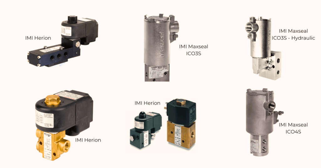
Once the operating principle, valve function, and installation philosophy have been established, the next step is selecting a product family that matches the application’s performance requirements. The Maxseal product families below support industrial pneumatic and hydraulic automation systems across a wide range of process and safety applications.
Maxseal ICO3S
The ICO3S family is widely applied in industrial valve automation systems requiring dependable switching, compact installation, and reliable venting. Available configurations support pneumatic and hydraulic actuator control for process automation, emergency shutdown systems, and hazardous industrial environments.
Typical Engineering Applications
- Emergency shutdown valve assemblies
- Quarter-turn valve automation
- Pneumatic and hydraulic actuator packages
- Hazardous-area installations
- General process automation systems
Maxseal ICO4S
The ICO4S family is designed for demanding valve automation applications requiring higher flow capacity, stable actuator control, and dependable operation under challenging process conditions. Available configurations support both pneumatic and hydraulic automation systems while maintaining compact integration with industrial valve assemblies.
Typical Engineering Applications
- Large pneumatic and hydraulic actuator packages
- Double-acting valve automation
- High air-demand applications
- Critical process isolation valves
- Heavy-duty industrial installations
Engineering Note: Product family selection should follow the engineering decisions established throughout this guide, including operating principle, valve function, mounting configuration, actuator compatibility, operating pressure, and environmental requirements. Detailed specifications, certifications, and configuration options are presented within the dedicated product pages for each product family.
Engineering Challenges & Practical Considerations
The following engineering discussions reflect practical questions encountered during design reviews, EPC projects, commissioning, shutdown planning, maintenance activities, and modernization of industrial valve automation systems.
Design Engineering
Can increasing solenoid valve Cv compensate for restrictions elsewhere in the pneumatic circuit?
Not always. Increasing Cv may improve airflow through the valve, but actuator ports, tubing diameter, fittings, exhaust capacity and actuator design frequently become the limiting factors. The entire pneumatic circuit should be evaluated before increasing valve size.
When should a pilot-operated solenoid valve be avoided even if it provides the required flow capacity?
Pilot-operated valves depend on sufficient operating pressure. Applications with unstable air supply, low differential pressure or intermittent pressure availability may require a direct-acting design despite its lower flow capacity.
When does a NAMUR-mounted valve offer an engineering advantage over an inline installation?
NAMUR mounting reduces tubing, leak paths and installation footprint while improving maintenance accessibility. Inline mounting remains preferable where installation flexibility or remote valve positioning is required.
Commissioning & Troubleshooting
Why does the actuator respond slowly even though the solenoid valve energizes correctly?
Electrical switching confirms only that the coil has been energized. Pneumatic pressure, exhaust restrictions, actuator friction, tubing arrangement, quick exhaust devices and actuator sizing should all be verified before concluding that the solenoid valve is responsible.
Why can identical solenoid valves produce different actuator stroke times?
Stroke time depends on the complete actuator package. Actuator air volume, spring characteristics, supply pressure, tubing configuration and exhaust capacity often have greater influence than the valve itself.
Which engineering checks should be completed before replacing a suspected faulty solenoid valve?
Verify supply pressure under operating conditions, coil voltage under load, pneumatic connections, manual override position, contamination, actuator movement and exhaust path before replacing the valve.
Reliability & Lifecycle
When does reducing coil power become an engineering advantage rather than simply an energy-saving measure?
Lower power coils can reduce cabinet heat, improve coil insulation life, decrease UPS loading and reduce power supply capacity requirements. The selected coil must still provide adequate magnetic force throughout the specified voltage and temperature range.
Does continuous coil energization reduce solenoid valve service life?
Continuous duty increases thermal loading on the coil and electrical insulation. Selecting the appropriate duty rating, ambient temperature limits and power management strategy can improve long-term reliability.
Can an existing valve automation package be improved without replacing the actuator?
Frequently. Reviewing valve configuration, tubing layout, pneumatic accessories and actuator integration often identifies opportunities to improve switching performance while retaining the installed actuator and process valve.
Can the same solenoid valve technology be used in both pneumatic and hydraulic automation systems?
Although the electromagnetic switching principle is similar, pneumatic solenoid valves and hydraulic directional control valves are designed for different operating media, pressure ranges, flow characteristics, sealing arrangements, and circuit architectures. Hydraulic systems typically operate at significantly higher pressures and require valve designs compatible with hydraulic fluid, while pneumatic systems are optimized for compressed air control. Product selection should therefore be based on the complete fluid power system rather than the electrical switching function alone.
Standards & Project Compliance
Does ATEX certification alone satisfy hazardous-area project requirements?
No. Engineers should also verify equipment category, gas group, temperature class, ambient temperature limits, enclosure protection, cable entries and project-specific hazardous-area documentation before approving a replacement.
Which project documents should be reviewed before approving an alternative solenoid valve?
Review the valve datasheet, instrument index, hook-up drawing, cause-and-effect matrix, hazardous-area schedule, actuator documentation and project specifications to confirm technical compatibility before substitution.
Engineering Tip
During troubleshooting, replacing the solenoid valve should rarely be the first corrective action. Dynamic supply pressure, actuator air demand, tubing restrictions, exhaust capacity, manual override position, electrical supply under load and pneumatic accessories should all be verified before concluding that the valve itself is the source of the problem. This engineering approach often improves system reliability while avoiding unnecessary component replacement.
Discuss Your Valve Automation Requirements
Selecting an industrial solenoid valve involves more than matching voltage or port size. Actuator characteristics, pneumatic layout, operating pressure, installation constraints, hazardous-area requirements, and project specifications all influence the final engineering decision.
Engineering information that helps accelerate technical review:
- Valve and actuator datasheets
- Actuator type (spring-return or double-acting)
- Required valve function (2/2, 3/2 or 5/2)
- Operating pressure and available instrument air
- Required actuator stroke time
- Hazardous-area classification (if applicable)
- Existing pneumatic schematic or hook-up drawing
- Description of the operational issue or project objective
Engineering first. In many cases, improving switching performance does not require replacing the entire actuator package. Reviewing the pneumatic architecture, valve configuration, and installation details often identifies opportunities to improve reliability while retaining existing equipment.