
EN 15714-3: Pneumatic Part-Turn Actuators — Requirements, Testing and Selection Guide
EN 15714-3 is a key European standard for pneumatic part-turn valve actuators used in industrial valve automation. It establishes basic requirements for pneumatic part-turn actuators, including both double-acting and single-acting designs, for on-off and modulating control duties.
For engineers, however, compliance with EN 15714-3 is only one part of actuator selection. A compliant actuator can still perform poorly in service if it is incorrectly sized, exposed to unsuitable operating conditions, supplied with poor-quality instrument air, incorrectly installed, or inadequately integrated with the valve and control system.
The important engineering question is therefore not simply:
“Does the actuator comply with EN 15714-3?”
It is:
“Does the actuator meet the standard and is it correctly selected, sized, installed and integrated for the actual valve application?”
This guide explains what EN 15714-3 covers, what it requires, how it relates to actuator selection and ISO 5211, and how engineers should evaluate pneumatic part-turn actuators in practical industrial applications.
What Is EN 15714-3?
EN 15714-3 is a European standard that specifies basic requirements for pneumatic part-turn valve actuators, including double-acting and single-acting actuators used for on-off and modulating control duties.
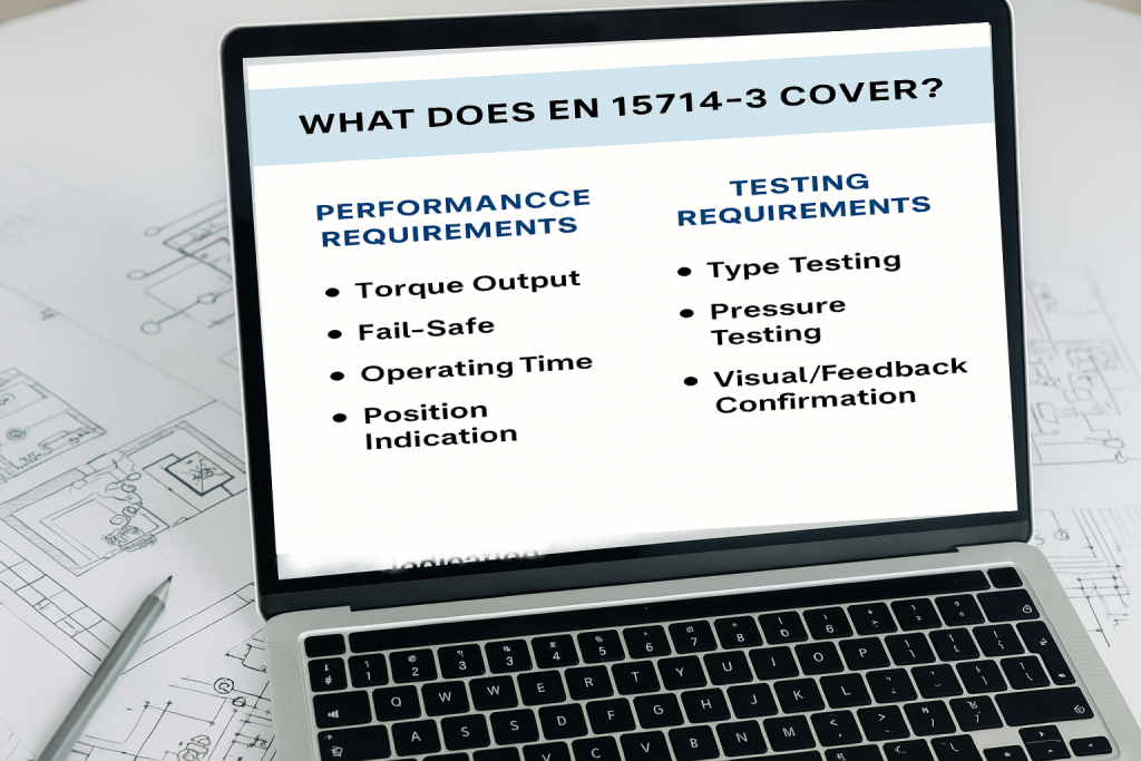
The standard addresses areas including actuator construction, performance, enclosure and corrosion protection, control and testing.
It is intended to establish a consistent technical basis for the design, manufacture, testing and specification of pneumatic part-turn actuators used in industrial valve automation.
EN 15714-3 is therefore primarily an actuator performance and testing standard. It should not be confused with a complete valve sizing standard, a Safety Instrumented System standard, or a substitute for application-specific engineering.
What Does EN 15714-3 Cover?
The scope of EN 15714-3 focuses on pneumatic part-turn valve actuators used for industrial valve automation.
The standard covers both:
- Double-acting pneumatic actuators
- Single-acting pneumatic actuators
and addresses their use in:
- On-off control duties
- Modulating control duties
Typical applications include automated quarter-turn valves such as:
- Ball valves
- Butterfly valves
- Plug valves
Common pneumatic part-turn actuator technologies include rack-and-pinion and scotch-yoke designs, depending on the required torque characteristic, valve application and operating conditions.
The standard does not apply universally to every pneumatic actuator configuration. For example, pneumatic actuators that are integral parts of control valves and pneumatic actuators designed for permanent immersion in fresh or seawater are outside the stated scope.
Why EN 15714-3 Matters in Valve Automation
A pneumatic actuator is the mechanical power source that converts pneumatic energy into the torque required to operate a part-turn valve.
If the actuator does not provide the required torque, speed or fail-safe performance, the valve automation system may not perform as intended.
Actuator performance can affect:
- Valve opening and closing
- Emergency shutdown response
- Process isolation
- Operational availability
- Maintenance requirements
- Equipment reliability
- Safety-related final element performance
EN 15714-3 provides a standardized engineering framework for evaluating important actuator characteristics. However, the standard does not eliminate the need to evaluate the actual valve, process and operating environment.
What Does EN 15714-3 Require?
EN 15714-3 addresses several areas relevant to pneumatic part-turn actuator performance and testing.
Actuator Performance
The actuator must be capable of delivering its specified performance under the defined operating conditions.
For engineers, this means that published actuator performance data should be interpreted together with the relevant pneumatic supply pressure, actuator configuration and operating conditions.
Torque Characteristics
Torque is one of the most important parameters when evaluating a pneumatic part-turn actuator.
The actuator must provide a torque characteristic suitable for the specified application and operating conditions.
However, actuator torque data alone does not determine whether an actuator is correctly sized for a valve. The required valve torque must first be understood.
Operating Performance
Actuator operating characteristics, including movement and response under defined conditions, are part of the performance evaluation.
Actual operating time in a plant can differ from catalogue values because of supply pressure, tubing, fittings, solenoid valves, restrictions, ambient conditions and valve load.
Single-Acting and Fail-Safe Operation
For single-acting actuators, stored spring energy provides movement when the pneumatic supply is removed.
The required fail position may be:
- Fail close
- Fail open
- Other application-specific safe position
The required fail-safe torque must therefore be evaluated against the actual valve torque requirement throughout the relevant portion of the valve stroke.
Enclosure and Environmental Protection
EN 15714-3 also addresses enclosure and environmental protection requirements.
The actuator specification should therefore be evaluated against the actual installation environment, including outdoor exposure, humidity, dust, corrosive atmosphere, temperature and other environmental conditions.
Testing
Testing is an important part of the standard because it provides a defined basis for demonstrating actuator performance under specified conditions.
The engineering significance of a test result, however, depends on understanding the test conditions and their relationship to the actual application.
Torque: The Most Important Selection Parameter
One of the most common actuator selection mistakes is choosing an actuator based only on the nominal valve size.
Valve size does not determine actuator size by itself.
Actuator selection should start with the torque required by the valve.
Depending on the valve design, relevant torque values may include:
- Breakaway torque
- Running torque
- Seating torque
- Unseating torque
- Maximum shaft torque
- Torque associated with process pressure
The required actuator torque should then be evaluated across the complete operating cycle rather than at only one point.
A simplified engineering relationship is:
Available actuator torque > required valve torque × appropriate engineering margin
The actual sizing method should follow the valve manufacturer’s data, actuator manufacturer’s sizing methodology and project requirements.
How to Select a Pneumatic Part-Turn Actuator
EN 15714-3 provides a technical framework, but actuator selection remains an application-specific engineering task.
A practical selection process should consider the following parameters.
1. Identify the Valve Type
Determine whether the actuator will operate a butterfly valve, ball valve, plug valve, damper or another part-turn device.
Different valve designs can have significantly different torque characteristics.
2. Determine Required Valve Torque
Obtain reliable torque data from the valve manufacturer or engineering calculation.
Consider breakaway, running and seating requirements where applicable.
3. Determine Available Pneumatic Pressure
Actuator torque depends on the available pneumatic supply pressure and actuator design.
Do not size the actuator only from the maximum nominal air pressure. The minimum available operating pressure may be more important for determining the worst-case actuator output.
4. Select Double-Acting or Single-Acting Configuration
Choose the actuator configuration according to the process function and failure philosophy.
Double-acting actuators use pneumatic energy for both directions of movement.
Single-acting spring-return actuators use pneumatic energy in one direction and stored spring energy in the other.
5. Evaluate Fail-Safe Requirements
For safety-related applications, determine the required fail position and verify that the actuator provides sufficient torque under the relevant worst-case conditions.
6. Check the Valve-to-Actuator Interface
Verify the mechanical interface between the valve and actuator, including flange dimensions, drive dimensions and coupling requirements.
ISO 5211 is the key international reference for part-turn actuator attachments to industrial valves. The current published edition is ISO 5211:2026.
7. Evaluate Operating Environment
Consider:
- Ambient temperature
- Humidity
- Corrosive atmosphere
- Dust
- Outdoor exposure
- Marine or offshore conditions
- Hazardous-area requirements
8. Evaluate Duty and Cycling
The required number of operating cycles and the nature of the duty can influence actuator selection, maintenance and expected service life.
9. Evaluate Accessories
The complete automation package may require:
- Solenoid valves
- Filter regulators
- Limit switches
- Position transmitters
- Positioners
- Partial Stroke Testing systems
- Local control devices
10. Verify the Complete Assembly
The final engineering check should consider the valve, actuator and automation accessories as one functional package.
Double-Acting vs Single-Acting Pneumatic Actuators
| Characteristic | Double-Acting | Single-Acting / Spring-Return |
|---|---|---|
| Power source | Pneumatic energy in both directions | Pneumatic energy plus spring energy |
| Fail-safe movement | Requires suitable system architecture | Provided by spring action when supply is lost |
| Typical application | General automation and applications requiring powered movement in both directions | Applications requiring a defined fail position |
| Design consideration | Available air pressure and torque in both directions | Spring torque and pneumatic torque throughout the stroke |
| Safety-related use | Possible with appropriate system architecture | Common where a defined mechanical fail position is required |
The choice should be based on the actual process function rather than simply on actuator preference.
Spring-Return Actuators and Fail-Safe Torque
Spring-return actuators require particular attention because the available spring torque changes throughout the actuator stroke.
The engineering question is not simply:
“Does the actuator have enough nominal spring torque?”
It is:
“Does the actuator provide sufficient torque throughout the required fail-safe movement under the worst-case operating conditions?”
This evaluation should consider:
- Minimum pneumatic supply pressure
- Spring torque at relevant positions
- Valve breakaway torque
- Valve running torque
- Valve seating torque
- Process pressure effects
- Environmental effects
- Required safety margin
For emergency shutdown applications, the fail-safe torque calculation is particularly important because a nominal actuator rating does not by itself demonstrate that the complete valve assembly will reach its required safe position.
EN 15714-3 and ISO 5211: Different Standards, Different Roles
EN 15714-3 and ISO 5211 are related to part-turn actuator applications, but they address different engineering aspects.
| Standard | Primary Engineering Role |
|---|---|
| EN 15714-3 | Requirements and testing framework for pneumatic part-turn valve actuators |
| ISO 5211 | Mechanical attachment and interface dimensions for part-turn actuators and industrial valves |
ISO 5211:2026 specifies requirements for the attachment of part-turn actuators, including relevant flange dimensions, driving component dimensions and reference torque values for interfaces and couplings.
Therefore:
EN 15714-3 answers actuator performance and testing questions.
ISO 5211 addresses the mechanical actuator-to-valve interface.
These standards should not be treated as interchangeable.
EN 15714-3 and Safety-Related Part-Turn Actuators
A pneumatic part-turn actuator may be used as part of a safety-related final element in an Emergency Shutdown System or Safety Instrumented Function.
However, EN 15714-3 compliance does not by itself establish a SIL capability or prove the performance of a complete Safety Instrumented Function.
Functional safety is addressed through the applicable safety lifecycle and standards, including:
- IEC 61508
- IEC 61511
A simplified Safety Instrumented Function can be represented as:
Sensor → Logic Solver → Final Element
The automated valve assembly normally forms part of the final element subsystem.
The assessment of a safety-related actuator therefore needs to consider more than actuator compliance. It may include:
- Actuator architecture
- Valve performance
- Solenoid valve architecture
- Energy supply
- Diagnostic coverage
- Proof Test strategy
- Failure data
- Common cause considerations
- Required response time
- Complete SIF architecture
This distinction is critical:
EN 15714-3 compliance is not equivalent to SIL certification.
What EN 15714-3 Does Not Establish
EN 15714-3 provides important actuator requirements, but compliance with the standard does not automatically demonstrate that an actuator is suitable for every application.
Engineers must still evaluate application-specific factors such as:
- Actual valve torque requirements
- Actuator sizing
- Required safety margins
- Process pressure effects
- Minimum available air pressure
- Instrument air quality
- Installation configuration
- Environmental conditions
- Hazardous-area requirements
- Control system integration
- Functional safety requirements
- Maintenance strategy
The standard provides a technical foundation. It does not replace application engineering.
Why an EN 15714-3-Compliant Actuator Can Still Fail in Service
Compliance testing is performed under defined conditions. Industrial service can introduce conditions that differ significantly from those used during testing.
Incorrect Actuator Sizing
An undersized actuator may not have sufficient torque to overcome the actual valve resistance, particularly during breakaway or seating.
Insufficient Torque Margin
Valve friction, process conditions and mechanical degradation can change over the equipment lifecycle. An actuator selected with inadequate engineering margin may become unreliable as the valve ages.
Poor Instrument Air Quality
Water, oil, particulates and unstable pressure can affect pneumatic components and reduce actuator reliability.
Incorrect Spring Selection
A spring-return actuator must provide sufficient spring torque for the required fail-safe movement under the relevant worst-case conditions.
Incorrect Installation
Misalignment between the valve and actuator can introduce mechanical loading, increased friction and premature wear.
Unsuitable Environmental Conditions
Corrosion, temperature extremes, humidity, offshore exposure and aggressive atmospheres can influence long-term actuator performance.
Inadequate Automation Integration
An actuator may perform correctly as a standalone mechanical device while the complete valve automation package performs poorly because of restrictions, solenoid selection, instrumentation, control logic or insufficient energy supply.
How Operating Conditions Affect Pneumatic Actuator Performance
Actuator catalogue performance should never be separated from the operating conditions under which that performance is required.
Air Pressure
Available pneumatic pressure directly affects actuator output torque. The minimum credible operating pressure should therefore be considered during sizing.
Temperature
Temperature can influence seals, lubricants, materials, spring performance and pneumatic behaviour.
Valve Friction
Valve friction can increase over time because of wear, corrosion, process deposits or changes in operating conditions.
Process Pressure
Process pressure can influence valve torque, particularly for certain valve designs and operating conditions.
Installation
Mechanical alignment and correct coupling are essential for reliable torque transmission.
Actuator Selection for Safety-Related Applications
When a pneumatic part-turn actuator operates an ESD valve or another safety-related valve, the selection process should begin with the required safety function.
The engineer should define:
- Required safe position
- Required valve stroke
- Required response time
- Minimum available pneumatic pressure
- Required fail-safe torque
- Normal operating torque
- Environmental conditions
- Required diagnostic functions
- Solenoid valve architecture
- Proof Test requirements
- Functional safety requirements
The actuator should then be evaluated as part of the complete automated valve assembly.
This is particularly important because the final element may include the valve, actuator, solenoid valve, pneumatic components, feedback devices and associated control interfaces.
EN 15714-3 and Complete Valve Automation
A pneumatic actuator rarely operates as an isolated component.
A typical automated part-turn valve package may include:
- Process valve
- Pneumatic actuator
- Solenoid valve
- Filter regulator
- Limit switches
- Position transmitter
- Positioner where required
- Partial Stroke Testing equipment
- Local control components
- Safety PLC or SIS interface
Each component can influence the overall performance of the automated valve.
For this reason, actuator compliance should be treated as one element within a broader valve automation engineering assessment.
Common Pneumatic Actuator Selection Mistakes
1. Selecting by Valve Size Alone
Valve size does not provide sufficient information for actuator sizing. Required torque must be evaluated.
2. Using Maximum Air Pressure for Sizing
The actuator should be checked against the minimum credible operating pressure, not only the maximum nominal supply pressure.
3. Ignoring Breakaway Torque
The actuator may require significantly more torque to initiate valve movement than to maintain movement.
4. Ignoring Seating Torque
For some valve designs, seating or unseating torque can determine the required actuator size.
5. Treating Spring-Return Torque as a Single Number
Spring torque changes with actuator position and must be evaluated across the required fail-safe movement.
6. Confusing EN 15714-3 Compliance with SIL Capability
Actuator performance compliance and functional safety assessment are different engineering questions.
7. Ignoring the Actuator-to-Valve Interface
Mechanical compatibility must be verified, including flange, drive and coupling requirements.
8. Ignoring the Complete Automation Package
Solenoid valves, pneumatic restrictions, feedback devices and control interfaces can affect actual system performance.
Engineering Selection Checklist
Before approving a pneumatic part-turn actuator for an industrial valve application, verify the following:
| Engineering Check | Verification |
|---|---|
| Valve type | Confirmed |
| Required breakaway torque | Verified |
| Required running torque | Verified |
| Required seating torque | Verified where applicable |
| Minimum pneumatic supply pressure | Confirmed |
| Actuator torque output | Checked against valve requirements |
| Torque safety margin | Defined and justified |
| Double-acting / single-acting | Selected according to process function |
| Fail position | Defined where applicable |
| Fail-safe torque | Verified across required stroke |
| Valve-to-actuator interface | Verified |
| ISO 5211 interface | Checked where applicable |
| Environmental conditions | Confirmed |
| Hazardous-area requirements | Checked where applicable |
| Cycle / duty requirements | Confirmed |
| Automation accessories | Selected and compatible |
| Functional safety requirements | Evaluated where applicable |
EN 15714-3 vs IEC 61508 and IEC 61511
| Aspect | EN 15714-3 | IEC 61508 / IEC 61511 |
|---|---|---|
| Primary focus | Pneumatic part-turn actuator requirements | Functional safety |
| Primary object | Actuator | Safety-related system / SIF / SIS lifecycle |
| Performance testing | Yes | Part of the overall safety lifecycle |
| Valve sizing | Not a substitute for application-specific sizing | Application-specific safety assessment |
| SIL determination | Not established by actuator compliance alone | Within the functional safety framework |
| Safety lifecycle | Not the primary purpose | Core requirement |
An actuator may comply with EN 15714-3 and still require additional evaluation before it is selected as part of a SIL-rated Safety Instrumented Function.
Frequently Asked Questions
What is EN 15714-3?
EN 15714-3 is a European standard specifying basic requirements for pneumatic part-turn valve actuators, including double-acting and single-acting actuators used for on-off and modulating control duties.
What type of actuators are covered by EN 15714-3?
The standard covers pneumatic part-turn valve actuators, including double-acting and single-acting designs. Typical industrial technologies include rack-and-pinion and scotch-yoke arrangements, depending on the application.
Does EN 15714-3 apply to quarter-turn actuators?
Yes. Pneumatic part-turn actuators are commonly used to operate quarter-turn valves such as butterfly, ball and plug valves.
Does EN 15714-3 cover actuator selection?
EN 15714-3 includes guidelines related to actuator selection. However, application-specific engineering is still required to determine valve torque, operating conditions, safety margins and the appropriate actuator configuration.
Does EN 15714-3 specify valve torque?
EN 15714-3 does not replace the application-specific determination of the torque required by the valve. Engineers must obtain or calculate the actual valve torque and then select an actuator capable of providing the required output under the relevant operating conditions.
What is the difference between EN 15714-3 and ISO 5211?
EN 15714-3 focuses on pneumatic part-turn actuator requirements and testing. ISO 5211 focuses on the mechanical attachment interface between part-turn actuators and industrial valves.
Is EN 15714-3 related to SIL?
EN 15714-3 is not a SIL standard. SIL and functional safety assessment are addressed through applicable functional safety frameworks such as IEC 61508 and IEC 61511. Compliance with EN 15714-3 alone does not establish SIL capability for a complete Safety Instrumented Function.
Can an EN 15714-3-compliant actuator still fail?
Yes. Compliance demonstrates performance against specified requirements and test conditions. Incorrect sizing, poor instrument air, unsuitable environmental conditions, installation problems or inadequate system integration can still cause field failures.
How do I select the right pneumatic part-turn actuator?
Start with the valve’s required torque, including breakaway, running and seating torque where applicable. Then evaluate minimum pneumatic supply pressure, actuator configuration, fail-safe requirements, safety margin, valve-to-actuator interface, environment, duty cycle and automation accessories.
What is the difference between double-acting and spring-return actuators?
A double-acting actuator uses pneumatic energy for both directions of movement. A single-acting spring-return actuator uses pneumatic energy in one direction and spring energy in the other, providing a defined mechanical action when pneumatic supply is lost.
What is ISO 5211:2026?
ISO 5211:2026 is the current international standard for part-turn actuator attachments to industrial valves. It specifies relevant interface dimensions for actuator attachment, driving components and reference torque values for specified interfaces and couplings.
Key Engineering Takeaways
- EN 15714-3 provides a standardized technical framework for pneumatic part-turn valve actuators.
- Compliance is not the same as application suitability. Correct actuator selection still requires application-specific engineering.
- Valve torque is the starting point for actuator sizing. Valve size alone is not sufficient.
- Minimum pneumatic pressure matters. Actuator output should be checked against the actual operating pressure range.
- Spring-return actuators require fail-safe torque evaluation throughout the required movement.
- ISO 5211 and EN 15714-3 have different roles. One addresses the actuator-to-valve interface; the other addresses pneumatic part-turn actuator requirements and testing.
- EN 15714-3 compliance does not establish SIL capability. Functional safety must be assessed within the applicable IEC 61508 / IEC 61511 framework.
- The complete automation package matters. Solenoid valves, pneumatic components, feedback devices and control interfaces can affect actual performance.
- Good actuator selection considers the complete lifecycle. Environment, maintenance, air quality, duty and future operating conditions should be considered before procurement.
Technical Perspective
EN 15714-3 should not be treated simply as a compliance statement on an actuator datasheet.
For an engineer, the standard is one part of a broader decision process that connects actuator performance with valve requirements, mechanical interface, pneumatic supply, operating environment and automation architecture.
A technically correct selection process can therefore be summarized as:
Understand the valve → determine the required torque → define operating conditions → select the actuator → verify the interface → evaluate the automation package → verify safety requirements where applicable.
This approach is particularly important for critical process applications where actuator performance directly influences process isolation, emergency shutdown and equipment availability.
The objective should not be to select an actuator simply because it complies with a standard.
The objective is to select an actuator that complies with the applicable requirements and performs reliably within the actual valve automation system.
Technical Standards and References
- EN 15714-3 — Industrial valves — Actuators — Part 3: Pneumatic part-turn actuators.
- ISO 5211:2026 — Industrial valves — Part-turn actuator attachments.
- IEC 61508 — Functional safety of electrical/electronic/programmable electronic safety-related systems.
- IEC 61511 — Functional safety — Safety instrumented systems for the process industry sector.
- IEC 60529 — Degrees of protection provided by enclosures.
- ISO 8573-1 — Compressed air — Contaminants and purity classes.
Always verify the applicable edition of each standard, project specifications, manufacturer documentation and end-user requirements before using a standard as a design or procurement requirement.
Related Valve Automation Topics
Need Help Selecting a Pneumatic Part-Turn Actuator?
Selecting a pneumatic actuator for an industrial valve should begin with the actual valve requirements rather than the actuator catalogue alone.
NordenFlow can support the technical evaluation of pneumatic valve automation packages, including actuator selection, valve-to-actuator compatibility, instrumentation, solenoid valves, fail-safe configurations and application-specific automation requirements.
Start with the valve requirement. Verify the torque. Check the operating conditions. Then select the appropriate actuator technology.