

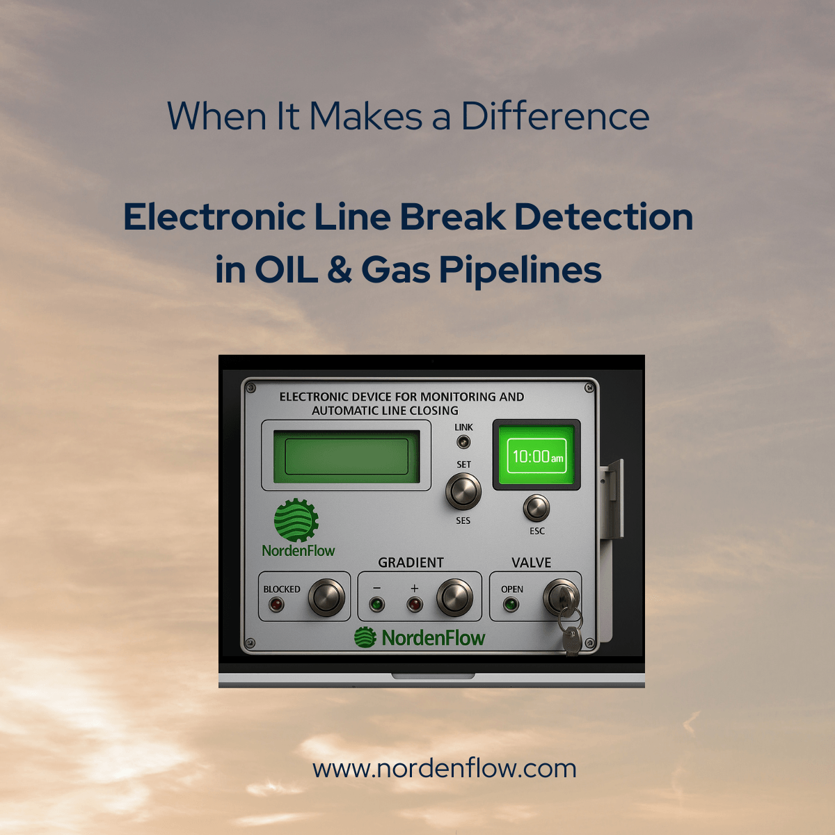
Electronic Line Break Detection in Pipelines: Principles, Applications and Engineering Considerations
Electronic Line Break Detection provides a way to identify abnormal pipeline conditions using electronic instrumentation, control logic and process measurements rather than relying only on mechanical line-break devices. When properly engineered, an electronic line break detection system can support rapid emergency isolation by detecting pressure, flow or other process signatures associated with a significant pipeline rupture.
For long-distance pipelines and high-consequence fluids, the engineering challenge is not simply detecting a pressure drop. The system must distinguish a genuine line-break signature from normal pipeline transients, operating changes and instrumentation disturbances, then initiate the appropriate isolation response.
This article explains the principles of electronic line break detection, compares electronic and mechanical approaches, discusses the role of pressure and flow measurements, and examines integration with Emergency Shutdown (ESD) systems and automated isolation valves.
What Is Electronic Line Break Detection?
Electronic Line Break Detection is a pipeline protection function that uses electronic field measurements and control logic to identify conditions that may indicate a major line break or rupture.
Depending on the application, the detection logic may evaluate one or more process parameters, including:
- Pipeline pressure
- Rate of pressure change (dP/dt)
- Flow rate
- Pressure differential
- Upstream and downstream process conditions
- Flow imbalance or mass-balance information
- Multiple measurement points along the pipeline
The measured signals are processed by a PLC, RTU, safety system or other control architecture. If the defined line-break criteria are satisfied, the logic can initiate an emergency isolation function through the associated valve automation system.
Therefore, electronic line break detection should not be considered simply a pressure switch with a lower set point. It is better understood as a measurement, decision and isolation architecture.
Why Is Pipeline Line Break Detection Challenging?
A pipeline does not operate under completely static conditions. Pressure and flow continuously change as a result of normal process operations, valve movements, pump or compressor behavior, temperature changes, elevation differences and changes in operating conditions.
A significant pipeline rupture can also generate rapid pressure and flow changes. However, the magnitude and propagation of these changes depend on the pipeline, fluid and operating conditions.
This creates the fundamental engineering challenge:
How can the detection system distinguish a genuine line-break condition from a normal or expected process transient?
A reliable detection strategy therefore requires more than selecting a single pressure threshold. The detection criteria, instrumentation, signal quality, response time, logic and isolation philosophy must be considered together.
Mechanical vs Electronic Line Break Detection
Mechanical and electronic line-break systems can both be used to support automatic pipeline isolation, but they approach the detection problem differently.
| Engineering Aspect | Mechanical Line Break Detection | Electronic Line Break Detection |
|---|---|---|
| Detection principle | Mechanical or hydraulic/pneumatic response to defined process conditions | Electronic measurement combined with programmable control logic |
| Typical measurements | Pressure or mechanical process response | Pressure, dP/dt, flow and other process variables |
| Logic flexibility | Generally limited by the mechanical device and configuration | Can be configured using programmable logic and multiple parameters |
| Diagnostics | Generally limited | Can provide electronic diagnostics and status information |
| SCADA integration | Limited or requires additional instrumentation | Natively suited to PLC, RTU and SCADA architectures |
| Multiple process inputs | Generally limited | Can combine multiple signals and detection criteria |
| Adaptability | Dependent on mechanical design and settings | Logic can be adapted to project-specific operating conditions |
This does not mean that electronic detection is automatically superior in every application. The appropriate architecture depends on the pipeline, fluid, operating conditions, required response time, consequence of failure, instrumentation availability and overall safety philosophy.
How Does Electronic Line Break Detection Work?
A typical electronic line break detection architecture can be divided into four functional layers:
- Process measurement — pressure, flow and other relevant variables are measured in the pipeline.
- Detection logic — the measurements are evaluated against defined line-break criteria.
- Shutdown decision — the control or safety logic determines whether the detected condition requires isolation.
- Valve actuation — the automated isolation valve moves to its defined safe position.
A simplified architecture can be represented as:
Pipeline Pressure / Flow
          ↓
   Field Transmitters
          ↓
 Electronic LBC Logic
          ↓
 Line-Break Decision
          ↓
     PLC / RTU / Safety Logic
          ↓
 Solenoid / Hydraulic Control
          ↓
 Gas-over-Oil / Electro-Hydraulic Actuator
          ↓
 Emergency Isolation Valve
The actual architecture should be developed according to the project-specific Cause & Effect, shutdown philosophy, instrumentation design and applicable safety requirements.
Pressure Monitoring for Line Break Detection
Pressure is one of the most commonly available process measurements for pipeline protection systems.
A major line break can result in a significant pressure disturbance. However, a fixed low-pressure threshold alone may not be sufficient to distinguish a genuine rupture from normal operating conditions.
For this reason, electronic systems can evaluate pressure as part of a broader detection strategy rather than treating pressure as an isolated trip parameter.
The location of pressure transmitters is also important. Measurement points, pipeline length, elevation profile, fluid properties and operating philosophy can influence how a pressure disturbance appears at the instrumentation.
The Role of dP/dt in Electronic Line Break Detection
The rate of pressure change (dP/dt) describes how quickly pipeline pressure changes with time.
A rapid pressure decrease may provide useful information when evaluating a potential line-break event. However, dP/dt should be regarded as one possible detection parameter, not as a universal line-break detection method.
The appropriate threshold and evaluation window depend on factors such as:
- Pipeline operating pressure
- Pipeline diameter and geometry
- Fluid properties
- Pipeline length
- Pressure transmitter response
- Normal operating transients
- Valve operating characteristics
- Pump or compressor behavior
- Pipeline elevation and boundary conditions
A robust electronic detection strategy may therefore combine dP/dt with other measurements and logical conditions instead of relying on a single calculated value.
Flow and Mass-Balance Information
Flow measurement can provide another useful source of information for line-break detection.
For pipelines where suitable measurement points are available, differences between upstream and downstream flow can contribute to the identification of abnormal conditions.
However, flow imbalance is not automatically equivalent to a line break. Meter accuracy, process inventory, fluid compressibility, measurement location, normal operating changes and transient behavior must be considered.
For this reason, flow information is generally most useful when integrated into an engineered detection algorithm rather than interpreted as a standalone trip signal.
Multi-Variable Electronic Line Break Detection
One of the principal advantages of electronic detection is the ability to evaluate multiple process variables within the same decision architecture.
Depending on the application, a line-break algorithm may consider combinations of:
- Pressure level
- Rate of pressure decrease
- Upstream pressure
- Downstream pressure
- Flow rate
- Flow imbalance
- Valve status
- Operating mode
- Time-based conditions
The objective is not simply to make the system more complicated. The objective is to improve discrimination between a genuine line-break condition and a normal process event.
When Should Electronic Line Break Detection Be Considered?
Electronic line break detection may be worth considering when the pipeline operating conditions make a simple mechanical detection approach difficult to configure or maintain.
Typical considerations include:
- Long-distance pipelines
- Remote pipeline sections
- High-consequence fluids
- Variable operating pressure
- Significant normal pressure transients
- Multiphase or two-phase flow
- Need for configurable detection logic
- Requirement for remote diagnostics
- Integration with PLC, RTU or SCADA systems
- Requirement for automated emergency isolation
- Difficult or impractical mechanical pilot installations
The decision should be based on an engineering assessment rather than on the assumption that electronic detection is inherently better than mechanical detection.
Electronic Line Break Detection in Two-Phase Pipelines
Two-phase or multiphase pipeline flow can create additional challenges for line-break detection.
When the transported medium contains more than one phase, pressure and flow behavior can differ significantly from that of a single-phase liquid pipeline. Normal operating fluctuations may become more complex, and a simple pressure threshold may not adequately represent the actual process state.
In such applications, the detection philosophy should consider the actual fluid composition, operating envelope, pressure profile and expected transient behavior.
Electronic detection can provide greater flexibility because multiple process measurements and logic conditions can be evaluated within the same control architecture. However, the detection algorithm still requires project-specific engineering and validation.
Electronic Line Break Detection for Sour Service and H₂S Pipelines
For pipelines carrying sour fluids or fluids containing hydrogen sulfide (H₂S), the consequence of an uncontrolled release can increase the importance of reliable emergency isolation.
In these applications, line-break detection should be considered as part of the wider process safety architecture rather than as an isolated instrumentation function.
The engineering assessment may need to consider:
- Release consequences
- Emergency isolation philosophy
- Detection reliability
- Instrument availability
- Hazardous-area requirements
- Power availability
- Communication architecture
- ESD logic
- Safe actuator response
The detection system does not replace the need for appropriate pipeline design, leak management, hazardous-area engineering or emergency response procedures.
Integration with ESD and Emergency Isolation
Electronic Line Break Detection can form part of an Emergency Shutdown (ESD) or emergency isolation strategy.
A typical functional sequence may be:
- Pipeline instruments detect abnormal process behavior.
- The electronic line-break logic evaluates the defined criteria.
- The system determines whether a line-break condition is present.
- An ESD or isolation command is generated according to the approved Cause & Effect.
- The valve control system activates the appropriate shutdown mechanism.
- The automated isolation valve moves toward its defined safe position.
- The valve position and system status can be reported to the control or supervisory system where applicable.
The exact implementation depends on the project’s safety requirements, control architecture and actuator design.
Integration with Gas-over-Oil and Electro-Hydraulic Actuation
Electronic line-break detection provides the detection and decision layer; the actuator provides the physical valve movement.
For pipeline emergency isolation, these functions can therefore be integrated into a complete valve automation architecture.
Gas-over-oil actuation can be used where stored energy and reliable emergency valve movement are required. Electronic line-break logic can provide the process-condition detection and shutdown command that initiates the required actuator response.
Similarly, electro-hydraulic actuation can be integrated into critical pipeline isolation applications where controlled hydraulic power and fail-safe valve operation are required.
The relationship can be summarized as:
Detection
    ↓
Electronic Line-Break Logic
    ↓
ESD / Shutdown Command
    ↓
Solenoid / Hydraulic Control
    ↓
Actuator
    ↓
Emergency Isolation Valve
For further information on actuator technologies used in pipeline isolation systems, see our Gas-over-Oil Actuator and Electro-Hydraulic Actuation solutions.
Electronic Line Break Detection vs Pipeline Leak Detection
Line break detection and pipeline leak detection are related but different functions.
A pipeline leak detection system may be designed to identify leakage over a broad range of leak sizes and operating conditions. A line-break detection function is generally focused on identifying conditions associated with a significant rupture or break that requires rapid isolation.
| Function | Primary Objective |
|---|---|
| Pipeline Leak Detection | Identify leakage and abnormal loss of product over the applicable detection range |
| Line Break Detection | Identify conditions indicating a significant pipeline break or rupture requiring isolation |
| ESD System | Execute the defined emergency shutdown or isolation action |
| Automated Isolation Valve | Physically isolate the pipeline section when commanded |
These functions may interact within an overall pipeline safety architecture, but they should not be treated as interchangeable.
Layered Line-Break Protection
Where justified by the project risk assessment, mechanical and electronic detection methods can be considered as complementary layers rather than mutually exclusive alternatives.
For example, a project may use electronic detection as part of the primary monitoring and control architecture while retaining an independent mechanical protection mechanism where appropriate.
The exact arrangement should be determined through the project’s safety philosophy, risk assessment, Cause & Effect and applicable engineering requirements.
The objective of layered protection is not simply to install more devices. Each layer should provide a clearly defined safety function and an appropriate degree of independence.
Engineering Considerations and Limitations
Electronic line break detection provides flexibility, but it is not a plug-and-play solution. Its performance depends on the quality of the engineering behind the detection architecture.
Important considerations include:
- Instrumentation: transmitter accuracy, response time, range and installation location.
- Detection logic: thresholds, time windows, voting and permissive conditions.
- Process dynamics: expected pressure and flow transients during normal operation.
- Fluid properties: compressibility, viscosity, phase behavior and operating temperature.
- Pipeline geometry: length, diameter, elevation and hydraulic characteristics.
- Power supply: availability and behavior during electrical failures.
- Communication: PLC, RTU and SCADA architecture where required.
- Actuator response: valve travel time, stored energy and fail-safe behavior.
- False trips: the detection logic must avoid unnecessary isolation caused by normal operating events.
- Failure response: the system should be evaluated for loss of instrumentation, communication or control power.
These considerations are particularly important for remote pipeline installations where maintenance access and troubleshooting may be difficult.
Typical Engineering Workflow
A practical electronic line-break detection project can follow a structured engineering process:
- Define the line-break scenario. Identify the pipeline section, fluid, operating conditions and credible rupture scenarios.
- Study process dynamics. Evaluate expected pressure and flow behavior during normal operation and abnormal events.
- Select measurement points. Determine suitable pressure and flow measurement locations.
- Develop detection criteria. Establish the process parameters, thresholds and time windows used by the detection logic.
- Define shutdown actions. Establish the relationship between line-break detection and ESD/isolation commands.
- Verify actuator performance. Confirm that the automated valve can achieve the required safe response.
- Review failure modes. Consider loss of power, instrumentation faults, communication failure and spurious trips.
- Validate the complete function. Test the detection, logic and valve response as an integrated safety function.
Frequently Asked Questions
What is electronic line break detection?
Electronic line break detection is a pipeline protection function that uses electronic process measurements and control logic to identify conditions that may indicate a significant pipeline break or rupture and, where required, initiate an isolation response.
How is electronic line break detection different from mechanical line break detection?
Mechanical systems generally rely on a mechanical, hydraulic or pneumatic response to defined process conditions, while electronic systems use transmitters and programmable logic to evaluate one or more process parameters.
Is dP/dt required for electronic line break detection?
No. dP/dt is one possible detection parameter. Depending on the application, an electronic system may use pressure, flow, pressure differential, flow imbalance or combinations of several process variables.
Can electronic line break detection be used with two-phase flow?
It can be considered for two-phase or multiphase pipelines, but the detection philosophy must account for the specific pressure and flow behavior of the transported fluid. Project-specific engineering and validation are required.
Can electronic line break detection initiate an ESD valve closure?
Yes, where the approved shutdown philosophy defines line-break detection as an initiating condition for emergency isolation. The detection logic, ESD system and actuator must be engineered as a coordinated functional architecture.
Can electronic and mechanical line break detection be used together?
Yes. Where justified by the project safety philosophy and risk assessment, mechanical and electronic detection can provide complementary protection layers. Their functions and independence should be clearly defined.
Is electronic line break detection the same as pipeline leak detection?
No. Line-break detection is generally focused on identifying significant rupture conditions that require rapid isolation, while leak detection systems may target a broader range of leakage scenarios.
What happens if power or instrumentation is lost?
The response depends on the system architecture. Power supply, instrument failure, communication loss and actuator fail-safe behavior should all be addressed during the engineering and safety assessment of the complete system.
Engineering Takeaways
- Electronic Line Break Detection is a measurement and decision architecture, not simply a pressure switch.
- dP/dt is one possible detection parameter and should not automatically be treated as a complete line-break detection method.
- Pressure, flow and other process variables can be combined to improve detection discrimination.
- Two-phase and multiphase pipelines require particular attention to process dynamics and normal operating transients.
- Line-break detection and general pipeline leak detection are related but different functions.
- Electronic detection can integrate naturally with PLC, RTU, SCADA and ESD architectures.
- The detection system and automated isolation valve should be engineered as one functional chain.
- Gas-over-oil and electro-hydraulic actuation can provide the physical valve response required for pipeline emergency isolation.
- Mechanical and electronic detection methods can be complementary where a layered protection philosophy is justified.
- The final detection architecture should always be based on the specific pipeline, fluid, operating conditions and safety requirements.
Standards and Engineering References
The applicable standards and engineering references for a line-break detection and emergency isolation project depend on the pipeline type, jurisdiction, safety classification and overall system architecture.
Relevant engineering frameworks may include applicable requirements for:
- Pipeline leak and rupture detection
- Emergency shutdown and isolation systems
- Functional safety and safety instrumented systems
- Pipeline control and monitoring
- Hazardous-area instrumentation
- Automated valve and actuator design
For safety-related applications, standards such as IEC 61508 and IEC 61511 may be relevant where the line-break detection and shutdown function forms part of a safety instrumented function. Pipeline-specific requirements and project specifications should always be reviewed before selecting the final architecture.
Conclusion
Electronic Line Break Detection can provide a flexible approach to pipeline emergency isolation when conventional mechanical detection does not adequately address the operating conditions or required level of monitoring.
Its value is not simply the use of electronic instrumentation. The real engineering advantage comes from the ability to combine process measurements, configurable detection logic, system diagnostics and automated valve actuation within a coordinated protection architecture.
For demanding pipeline applications, the key question is therefore not whether electronic detection is newer than mechanical detection. The key question is whether the selected detection architecture can reliably distinguish a genuine line-break condition from normal pipeline behavior and initiate the required isolation response.
NordenFlow approaches valve automation and pipeline isolation from this system-level perspective, connecting process measurement, line-break detection, ESD logic and actuator technology to support practical and application-specific engineering solutions.