

Functional Safety in Valve Automation — Why the Solenoid Valve Is Often the Weakest Link
In the design of safety-instrumented systems (SIS), engineering teams typically focus most of their technical attention on large control valves and heavy pneumatic actuators. Because these large physical assemblies execute the final torque demands, they absorb the bulk of the engineering hours and procurement budget.
The Electro-Pneumatic Trigger Point
However, field data reveals that real-world loops rarely fail due to these major assemblies. Instead, catastrophic failures usually stem from a smaller, often overlooked interface component: the solenoid valve.
Positioned as the physical bridge between safety logic solvers and the actuator, this valve is the absolute trigger point for the entire safety function. If it stalls, your safety loop fails completely.
Why Functional Safety is More Than a Certified Component
A common misunderstanding in industrial project execution is treating a Safety Integrity Level (SIL) rating as a standalone stamp belonging to an individual piece of hardware. In reality, SIL is a strict system-level evaluation determined by calculating the **Average Probability of Failure on Demand ($PFD_{avg}$)** across the entire automated loop.
This math means that every inline component adds its own probability of failure to the system total. Because the highest-risk element sets the final limit for the entire loop, a poorly selected pilot solenoid will downgrade a SIL 3 valve assembly to a lower safety tier.
When a shutdown command occurs, the safety PLC drops power to the solenoid coil, which must instantly vent the actuator air header. If the internal spool or poppet fails to shift, the process valve remains locked in place, leaving the safety function completely unexecuted.
Why Internal Valve Design Matters: Poppet vs. Spool
Internal valve design directly affects how reliably a pilot element performs after sitting idle for long periods. Standard spool-type solenoids use dynamic O-rings that slide horizontally inside a metal bore.
In Emergency Shutdown (ESD) setups, these valves often remain static in the energized position for months or years. Over time, trace pipeline contaminants, sticky oil varnishes, and rubber degradation cause the dynamic seals to stick to the bore surface. This friction frequently causes the spool to jam when a trip signal finally occurs.
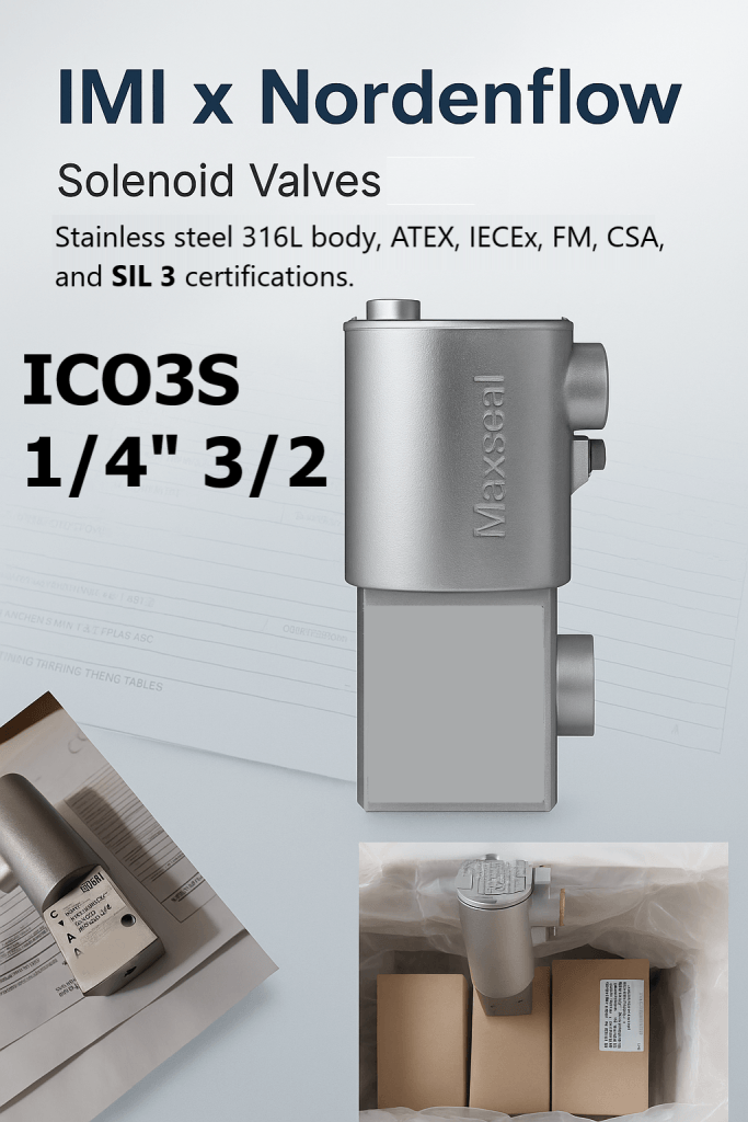
To eliminate this specific risk, high-integrity loops utilize **poppet-style** solenoid valves, such as premium solutions from **IMI Maxseal** or **Herion**. Poppet valves feature a vertical-lift design where the seal lifts directly off the seat rather than sliding against a wall.
Because this design uses no sliding seals, it remains highly resistant to sticking and easily clears out line particulates. This ensures instant mechanical movement even after years of continuous inactivity.
Safety Architecture Voting Matrix
The matrix below contrasts the operational behavior, safety availability, and false trip risks of common pilot voting architectures.
| Voting Configuration | Core Operational Mechanics | Field Risk & Availability Focus |
|---|---|---|
| 1oo1 (One out of One) | Single solenoid control path with no hardware redundancy. | High risk of nuisance trips; a single internal failure disables the loop. |
| 1oo2 (One out of Two) | Two solenoids placed in a parallel pneumatic path. Either valve can vent the line. | Maximizes safety availability; cuts $PFD_{avg}$ but increases risk of false trips. |
| 2oo2 (Two out of Two) | Two solenoids in a series path. Both must shift to execute a trip. | Eliminates false trips entirely; however, it reduces overall safety margins. |
| 2oo3 (Two out of Three) | Three-valve voting configuration blending parallel and series logic. | Provides optimal balance, securing maximum safety availability alongside fault tolerance. |
Environmental Factors Affecting Safety Performance
External site environments frequently introduce severe stress factors that challenge the structural safety of your pilot skids. In harsh offshore marine applications or subzero Nordic climates, environmental variables can quickly cause standard instrumentation components to fail.
Extreme cold drops internal seal flexibility, causing localized air leakage that bleeds out actuator pressure headers. Meanwhile, salty marine atmospheres accelerate galvanic corrosion across standard zinc-plated iron paths, causing internal plungers to bind.
Managing these harsh exposures requires moving past basic aluminum housings. High-integrity networks specify robust stainless steel enclosures (such as 316L) equipped with explosion-proof ATEX / IECEx certifications and high-temperature Class H coil insulation. This premium hardware protection shields the internal inductive core from water ingress and insulation tracking faults, keeping the emergency path reliable through severe seasonal shifts.
A Structured Engineering Framework for Safety Specification
To prevent your pilot solenoid from becoming the weak point in your safety chain, design teams should follow a comprehensive, system-level framework during specification:
- Calculate true loop $PFD_{avg}$ targets: Ensure your pilot component data aligns with your target control valve and actuator safety values.
- Select poppet valve configurations over spools: Eliminate dynamic sliding friction to protect systems from sticking during long idle periods.
- Match voting logic to plant risk targets: Implement 1oo2 or 2oo3 pneumatic piping arrays to optimize safety availability and prevent nuisance shutdowns.
- Specify rugged materials for harsh environments: Use 316L stainless steel bodies and specialized low-temperature fluorosilicone seals to handle harsh climates.
Frequently Asked Questions
What is the primary difference between functional safety and basic component reliability?
Component reliability measures the general time between failures during standard running cycles. Functional safety evaluates the probability that an integrated system will successfully execute its emergency shutdown function whenever a dangerous process condition occurs ($PFD_{avg}$).
Why are spool valves considered high-risk elements in safety-instrumented systems?
Spool valves use tight dynamic O-ring seals that slide within a tight metal bore. When left static for months at a time, these rubber seals develop a high breakout friction (“stiction”) or trap line contaminants, which can cause the valve to stick when an emergency trip is triggered.
How does a 1oo2 solenoid valve configuration increase overall system safety availability?
A 1oo2 configuration pipes two redundant solenoids in a parallel pneumatic path. If an internal component or sticky seal causes one valve to fail, the second valve can still vent the line safely, ensuring the emergency shutdown occurs successfully.
Key Takeaway for Plant Safety and Integrity Teams
Achieving a verified SIL target requires more than purchasing certified components; it requires a systematic approach that aligns internal valve mechanics with actual site conditions. Specifying rugged, lift-action poppet solutions like IMI Maxseal or Herion protects your automation loops from the stiction, contamination, and thermal stresses that compromise standard components. Focusing on precision component specification is the fastest way to eliminate unexpected plant downtime, protect your assets, and ensure robust functional safety across your facility.