How the IMI Maxseal Redundant Valve Manifold Improves SIS Availability and Functional Safety
In Safety Instrumented Systems (SIS), maintaining functional safety while ensuring high process availability is a tough engineering challenge. Emergency Shutdown (ESD) valves must operate instantly during a crisis. However, unnecessary spurious shutdowns cause massive production losses and high restart costs. Therefore, modern automation engineers increasingly deploy redundant solenoid architectures to eliminate single-point failures.
The Next Generation of Safety Control Element Design
The IMI Maxseal Redundant Valve Manifold (RVM) directly solves this operational conflict. By integrating multiple heavy-duty solenoid valves into a single compact block, the RVM systematically improves overall reliability.
Furthermore, this smart design increases real-time diagnostic coverage, removes complex external pipe connections, and simplifies hot-swappable maintenance. As a result, it fully supports high-integrity Safety Instrumented Functions (SIFs) in strict accordance with IEC 61508 guidelines.
What Is a Redundant Valve Manifold?
A Redundant Valve Manifold (RVM) is an integrated pneumatic or hydraulic block that Houses multiple solenoid valves. These internal valves work together using built-in mechanical voting logic, such as 1oo2, 2oo2, or 2oo3.
Instead of trusting a single solenoid to dump actuator air during an emergency, the RVM shares control across independent channels. This internal distribution lowers the average probability of failure on demand, known as PFDavg. Consequently, these robust assemblies secure critical automated isolation valves, protective turbine trip circuits, and high-consequence refinery safety loops.
Why Solenoid Redundancy Matters in Critical SIS Loops
Inside final control elements, the standard solenoid pilot valve represents a common potential point of mechanical failure. For example, a single burnt coil or stuck internal plunger can cause an unwanted, accidental process trip. Worse yet, it might freeze entirely and prevent the valve from closing during a true plant emergency.
Integrated redundant architectures easily eliminate these dangerous risks. They introduce reliable hardware fault tolerance, which lets you service components without taking the safety loop offline.
Specifically, installing an integrated RVM delivers several distinct engineering benefits:
- It eliminates dangerous single-point failures within the safety loop.
- It lowers the loop’s average probability of failure on demand (PFDavg).
- It drastically reduces the operational frequency of expensive spurious trips.
- It supports automated diagnostic testing programs, including Partial Stroke Testing (PST).
Available Voting Architectures Within the IMI Maxseal RVM
The IMI Maxseal RVM platform easily configures into multiple redundancy layouts. This allows project teams to balance safety targets and production uptime based on the specific safety loop requirements.
1oo2 Architecture (One-Out-Of-Two)
A 1oo2 setup utilizes two solenoid valves installed in a parallel pneumatic arrangement. In this loop, either channel can successfully trigger the safety action on its own. If either valve loses electrical power or receives a command, the system dumps actuator air immediately.
Therefore, this setup heavily prioritizes safety protection by maximizing emergency shutdown capability. However, it increases your risk of a nuisance trip if one coil fails.
2oo2 Architecture (Two-Out-Of-Two)
A 2oo2 arrangement requires both internal solenoids to drop out simultaneously before any shutdown action can physically occur. If only one valve trips due to a wiring fault, the alternative channel maintains air pressure to the actuator.
Consequently, this layout heavily maximizes production availability. It works perfectly for production-critical loops where accidental trips cause extreme financial damage.
2oo3 Architecture (Two-Out-Of-Three)
The 2oo3 architecture combines three independent solenoids in a smart two-out-of-three voting matrix. This setup delivers the ideal engineering balance for high-consequence plants. It safely tolerates a single channel failure without interrupting production or compromising safety protection. If one channel fails, the remaining two valves maintain full functional safety.
Technical Specifications of the IMI Maxseal RVM
The table below outlines the heavy-duty engineering parameters that make this manifold suitable for harsh industrial installations.
| Engineering Parameter | Official Specification | Real-World Plant Benefit |
|---|---|---|
| Solenoid Core Technology | IMI Maxseal ICO3 Platform | High-force, ultra-reliable safety performance. |
| Body Construction Material | 316L Stainless Steel (1.4404) | Excellent corrosion resistance in offshore environments. |
| Pneumatic Response Time | Less than 60 milliseconds (< 60 ms) | Extremely fast actuator venting during trips. |
| Internal Seat Leakage | Bubble Tight Sealing | Eliminates continuous, costly instrument air losses. |
| Max Pressure Boundary | 12 bar (174 psi) | Safely handles high-pressure heavy pneumatic actuators. |
| Ambient Temperature Range | -55°C to +90°C | Survives arctic environments and high-heat skids alike. |
Integrated Manifold Layout vs. Traditional Piping
Traditional redundant pilot hookups require separate standalone solenoid blocks, external stainless steel piping, and dozens of compression fittings. While that traditional layout functions, it introduces numerous physical leak points. It also increases your risk of installation errors during tight turnaround schedules.
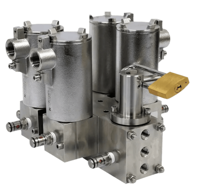
The integrated manifold design of the IMI Maxseal RVM combines all cross-over channels inside a single solid stainless block. This direct configuration reduces space requirements, drops weight constraints, and completely removes vulnerable intermediate piping.
Continuous Online Maintenance and Smart Diagnostics
Maintenance accessibility is another critical factor in continuous process facilities. For this reason, the IMI Maxseal RVM can feature an optional integrated maintenance bypass handle. This heavy-duty mechanical bypass lets operators isolate single solenoid channels for testing or replacement while the process continues running.
To ensure total safety, the assembly includes robust mechanical locking pins. These pins prevent accidental or unauthorized bypass activation. Additionally, optional visual flags provide clear status information, allowing technicians to check channel positions at a glance.
Typical Applications for High-Availability RVM Assemblies
Frequently Asked Questions
Can technicians safely swap a faulty solenoid coil on an RVM online?
Yes. When utilizing a 2oo3 voting layout or an integrated maintenance bypass model, you can safely swap out a single solenoid valve without tripping the process loop or losing safety protection.
What core benefit does the IMI Maxseal ICO3 solenoid core bring to this manifold?
The ICO3 is a highly reliable solenoid platform with high coil operating forces. It resists sticking caused by oil or particulate buildup in harsh instrument air lines.
How does an integrated block design save project execution costs?
The integrated manifold removes up to 70% of external fittings and connection pipework. This reduction slashes engineering drafting time, eliminates potential field leak paths, and accelerates loop commissioning.
Key Takeaway for Safety Engineers
The IMI Maxseal Redundant Valve Manifold delivers an engineered solution to improve SIS reliability. By supporting 1oo2, 2oo2, and 2oo3 voting setups inside a single block, the RVM helps engineers balance safety metrics and production availability. For high-consequence applications, this redundancy strategy is essential to maintain safety protection while avoiding expensive nuisance trips.