

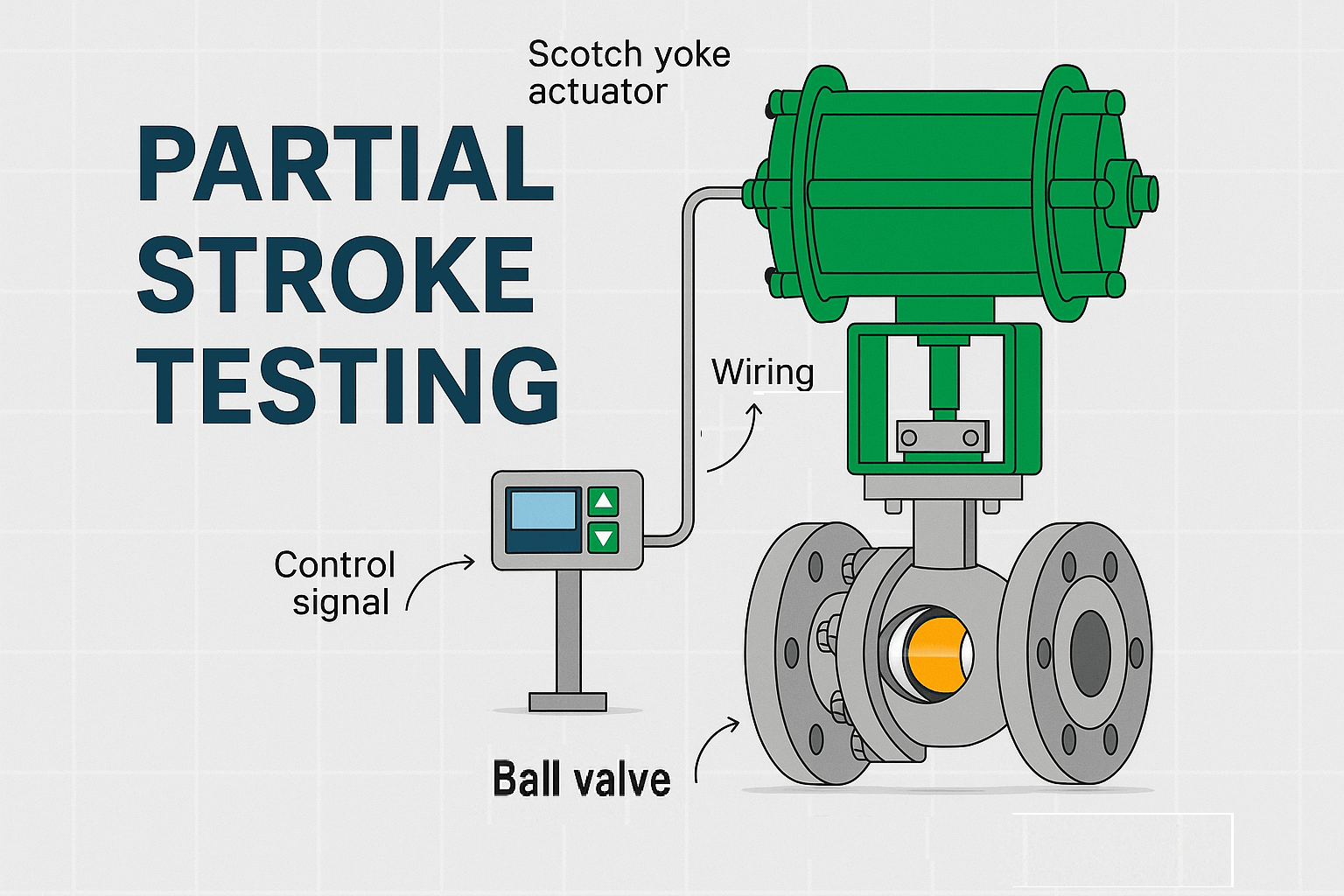
Partial Stroke Testing (PST): A Practical Guide for ESD and Shutdown Valves
Partial Stroke Testing (PST) is a diagnostic testing method used to partially move an automated shutdown valve without completing its full process stroke. It is commonly applied to Emergency Shutdown Valves (ESDVs) and other safety-related shutdown valves that may remain stationary for long periods but must operate reliably when a shutdown demand occurs.
PST can provide valuable information about selected failure modes affecting the valve, actuator and associated control components while reducing the operational impact normally associated with a full-stroke test. However, PST does not automatically replace full-stroke or proof testing. Its effectiveness depends on the valve and actuator architecture, the PST method, the failure modes covered, the test procedure and the requirements of the applicable safety lifecycle.
For maintenance and process automation engineers, the key question is therefore not simply “Can the valve move?” but:
“What evidence do we have that the complete automated shutdown valve will perform its required function when demanded?”
What Is Partial Stroke Testing?
Partial Stroke Testing, commonly abbreviated as PST, is a controlled test in which an automated shutdown valve is moved through a defined portion of its available travel and then returned to its normal operating position.
The purpose is to exercise selected parts of the final element without completing the full valve stroke that may be required during an actual emergency shutdown.
A typical PST may evaluate aspects of:
- Valve mechanical movement
- Actuator response
- Pneumatic or hydraulic energy availability
- Solenoid and control circuitry
- Position feedback
- Travel response
- Selected diagnostic parameters
The exact diagnostic coverage depends on the valve assembly and PST architecture.
PST is particularly relevant to shutdown valves because these valves may remain in their normal position for long periods. A valve that has not moved for months or years can develop degradation that may not be obvious during a visual inspection.
PST provides an opportunity to detect selected degradation before the valve is required to perform an actual shutdown function.
Why Is PST Used on ESD Valves?
Emergency Shutdown Valves are normally part of a protective process function. Under normal operating conditions, an ESD valve may remain fully open or fully closed and may move only when a shutdown demand occurs or when a scheduled test is performed.
This creates a particular reliability challenge.
Frequently operated equipment provides repeated opportunities for abnormal behavior to become visible. An infrequently operated shutdown valve may develop hidden failures while appearing normal during routine inspection.
Potential causes include:
- Increasing mechanical friction
- Actuator degradation
- Loss of pneumatic or hydraulic performance
- Solenoid valve problems
- Mechanical coupling problems
- Position-feedback problems
- Degraded seals or components
- Corrosion or environmental degradation
- Loss or degradation of the energy source
PST can provide an additional diagnostic layer by exercising selected parts of the automated valve assembly without routinely requiring a complete shutdown stroke.
This makes PST particularly useful where frequent full-stroke testing would create unacceptable operational disruption.
PST Is a Diagnostic Test, Not a Universal Proof-Test Replacement
One of the most important engineering distinctions is the difference between Partial Stroke Testing and proof testing.
A PST exercises only a defined portion of the valve travel and therefore does not necessarily expose every failure mode that could prevent the complete safety function from operating.
A full-stroke proof test provides a broader functional check because the valve is required to complete its specified operating stroke. The exact scope and coverage of a proof test depend on the safety function, test procedure and equipment architecture.
Therefore:
PST should normally be considered an additional diagnostic and testing measure within the overall safety lifecycle, not automatically as a replacement for the required proof-test strategy.
Where PST is used to support a safety instrumented function, its contribution must be evaluated using the actual failure modes, test coverage, test interval and functional-safety calculations applicable to that SIF.
Partial Stroke Test vs Full Stroke Test
| Aspect | Partial Stroke Test (PST) | Full Stroke Test (FST) |
|---|---|---|
| Valve movement | Defined portion of available travel | Complete specified operating stroke |
| Primary purpose | Diagnostic testing and detection of selected failure modes | Broader functional verification |
| Process impact | Usually lower when the application and architecture permit online testing | Potentially higher because full movement may affect the process |
| Failure coverage | Dependent on test architecture and travel range | Broader for failure modes exercised by the complete stroke |
| Seat shutoff verification | Generally not demonstrated by PST alone | Can be evaluated where the test procedure includes the relevant shutoff verification |
| Maintenance role | Additional diagnostic layer | Important part of the defined functional or proof-test strategy |
| Replacement for proof testing | Not automatically | Depends on the approved safety and testing strategy |
The correct approach is therefore not to choose PST or full-stroke testing as competing technologies. In many applications, the two methods serve different purposes within the overall maintenance and functional-safety strategy.
What Failure Modes Can PST Detect?
PST can detect selected failure mechanisms that affect the ability of an automated shutdown valve to move through the tested portion of its travel.
Depending on the equipment and test architecture, these may include:
- Increasing valve friction
- Stiction or abnormal mechanical resistance
- Actuator performance degradation
- Insufficient actuator energy
- Selected pneumatic or hydraulic problems
- Solenoid or control-circuit problems
- Mechanical coupling degradation
- Abnormal travel response
- Position-feedback abnormalities
- Unexpected changes in travel time or test signature
The value of PST increases when test results are recorded and compared over time rather than treated as a simple pass/fail event.
For example, a gradual increase in valve travel time may provide an early indication of degradation even when the valve still completes the defined PST successfully.
What PST Cannot Detect by Itself
PST should not be presented as a complete diagnostic test for every possible dangerous failure mode.
Depending on the valve and PST architecture, some conditions may remain outside the effective coverage of the test.
Examples can include:
- Failure modes outside the tested travel range
- Certain seat leakage conditions
- Some mechanical failures that are not exercised during the test
- Some feedback or instrumentation failures, depending on the feedback architecture
- Failure modes that are not represented by the selected diagnostic method
- Failures associated with components that are not included in the PST path
This is why the engineering assessment should begin with the intended safety function and its failure modes rather than with the PST device itself.
PST coverage is architecture-dependent. A PST system should be evaluated against the specific failure modes it is intended to detect.
How Partial Stroke Testing Works
A simplified PST sequence can be represented as:
PST command → control/interface device → solenoid or pneumatic circuit → actuator movement → valve partial travel → feedback/diagnostics → return to normal position
The exact architecture varies between applications and manufacturers.
A typical automated shutdown valve assembly may include:
- Process valve
- Pneumatic, hydraulic or electric actuator
- Solenoid valve or equivalent final-element interface
- Limit switches or position feedback
- PST device or diagnostic-capable positioner
- Safety PLC, SIS or control interface
- Local or remote diagnostic capability
The PST command initiates a controlled movement. The test system monitors the expected response and determines whether the measured behavior meets the defined test criteria.
The valve must then be returned to its normal operating position and its readiness for service must be confirmed.
PST Test Procedure
A PST procedure should be defined for the specific valve assembly and operating environment. It should not be based only on a generic percentage of valve travel.
1. Define the Test Objective
Identify what the PST is intended to verify and which failure modes are within the expected diagnostic coverage.
2. Confirm Process Conditions
Verify that the process is in a suitable condition for the planned valve movement and that the test can be performed without creating an unacceptable process or safety risk.
3. Verify Test Permissives
Confirm that the valve, actuator, control system and PST architecture are ready for the test and that required interlocks or permissives are satisfied.
4. Initiate the PST
Command the valve to move through the defined partial travel using the approved test method.
5. Monitor Valve Response
Monitor relevant parameters such as valve travel, actuator response, position feedback, travel time and other diagnostic information available from the system.
6. Evaluate the Test Result
Compare the measured response with the approved acceptance criteria and the established baseline where applicable.
7. Return the Valve to Normal Position
Verify that the valve returns correctly to its normal operating position.
8. Confirm Shutdown Readiness
Confirm that the valve and associated safety function remain available for a genuine shutdown demand.
9. Record the Result
Record the test date, valve identification, test method, measured parameters, result and any abnormal observations.
10. Review Abnormal Trends
A failed or degraded PST result should be evaluated as part of the maintenance process rather than simply reset and ignored.
PST Acceptance Criteria
There is no single universal PST acceptance value that should be applied to every ESD valve.
Acceptance criteria should be established by the approved engineering and test procedure for the specific valve, actuator, PST architecture and safety application.
Typical criteria may include:
- Successful completion of the defined partial travel
- Travel time within the specified limit
- Expected actuator response
- Valid position feedback
- Stable pneumatic or hydraulic performance where monitored
- Successful return to the normal operating position
- No abnormal diagnostic indication
- No unexpected change from the established baseline
For safety-related applications, acceptance criteria should be documented and controlled as part of the applicable testing and maintenance procedure.
Do not apply a generic 10%, 15% or 20% PST travel rule without confirming that value against the specific equipment, manufacturer documentation and project requirements.
How Often Should an ESD Valve Undergo PST?
PST frequency should be determined by the plant’s safety and maintenance strategy rather than by a universal interval.
The appropriate interval may depend on:
- Safety requirements
- Failure-rate assumptions
- Required safety integrity
- Diagnostic coverage
- Proof-test interval
- Valve and actuator technology
- Process constraints
- Manufacturer recommendations
- Operating history
- Previous PST results
For a safety instrumented function, changes to test intervals should be evaluated within the applicable functional-safety lifecycle and supporting calculations.
The Role of the Solenoid Valve in PST
The shutdown solenoid valve can be an important part of the automated final-element architecture.
Depending on the PST design, the solenoid and associated pneumatic circuit may participate directly in the test sequence.
Potential areas of concern include:
- Solenoid response
- Supply pressure
- Exhaust performance
- Internal leakage
- Valve spool or poppet movement
- Pneumatic tubing condition
- Control signal integrity
- Redundant solenoid architecture where applicable
A PST result should therefore be interpreted in the context of the complete final element rather than treating the PST device as an isolated component.
This is particularly important when troubleshooting an abnormal PST result. The problem may originate in the valve, actuator, solenoid, pneumatic circuit, feedback system or PST device.
PST and Functional Safety
When an automated shutdown valve forms part of a Safety Instrumented Function (SIF), PST should be considered within the overall functional-safety lifecycle.
IEC 61508 provides the generic functional-safety framework for electrical, electronic and programmable electronic safety-related systems. IEC 61511 provides the process-industry framework for Safety Instrumented Systems, including requirements related to specification, design, installation, operation and maintenance.
For a typical SIF:
Sensor → Logic Solver → Final Element
The automated shutdown valve is normally part of the final element subsystem.
Therefore, evaluating PST requires consideration of the complete safety function rather than the valve alone.
Does PST Increase SIL?
No. PST does not automatically increase the SIL of a safety instrumented function.
PST can contribute to the detection of selected dangerous undetected failures. Where its diagnostic effectiveness is appropriately established, that information may be considered in the functional-safety analysis and reliability calculations for the applicable safety function.
However, the resulting safety performance depends on the complete SIF, including:
- Sensor subsystem
- Logic solver
- Final element
- Failure rates
- Diagnostic coverage
- Test intervals
- Proof-test coverage
- Architecture
- Common-cause considerations
- Systematic capability
Therefore, statements such as “PST makes the valve SIL 3” are technically misleading unless they refer to a specific assessed architecture and safety calculation.
A more accurate engineering statement is:
PST can support the detection of selected dangerous failures in a safety-related final element and may contribute to the overall safety performance when properly incorporated into the functional-safety assessment.
PST, PFDavg and Diagnostic Coverage
Probability of Failure on Demand Average (PFDavg) is one of the parameters considered when evaluating low-demand safety instrumented functions.
Testing and diagnostics can influence the probability that certain dangerous failures remain undetected before a demand occurs.
However, PFDavg is not determined by PST alone.
A simplified engineering relationship is:
Safety performance = complete SIF architecture + failure data + diagnostics + test intervals + proof-test coverage + other lifecycle parameters
PST should therefore be evaluated as one element of the overall testing and diagnostic strategy.
For actual SIL verification or PFDavg calculations, the approved safety lifecycle methodology and project-specific failure data should be used.
Why PST Is Important for Infrequently Operated Shutdown Valves
An automated shutdown valve can remain in the same position for a long period while still being expected to operate immediately when a hazardous condition occurs.
This creates the possibility of hidden failures.
For example, an actuator seal may degrade without being obvious during a visual inspection. Mechanical friction may increase gradually. A solenoid may become unreliable. Instrument air quality may deteriorate. Feedback may become intermittent.
Without testing, some of these conditions may remain undetected until the valve is required to operate.
PST provides a controlled opportunity to exercise selected parts of the final element before an actual demand occurs.
PST and Condition Monitoring
The value of PST increases when test results are treated as condition data rather than as isolated pass/fail events.
A practical monitoring strategy can follow this sequence:
PST event → measured response → baseline comparison → trend analysis → maintenance decision
Relevant parameters may include:
- Travel time
- Actuator response
- Valve position
- Supply pressure
- Pressure decay or recovery where applicable
- Diagnostic status
- Test repeatability
A gradual change in these parameters can provide useful information for maintenance planning.
This moves PST beyond periodic testing toward a broader valve condition-monitoring strategy.
PST Maintenance Checklist
Valve and Mechanical Assembly
- Check for abnormal friction or resistance.
- Verify actuator-to-valve coupling condition.
- Check for corrosion or mechanical degradation.
- Review abnormal travel behavior.
Actuator
- Verify actuator sizing and operating capability.
- Check available energy.
- Review actuator response.
- Inspect seals and mechanical components as required.
Pneumatic or Hydraulic System
- Verify supply pressure.
- Check tubing and connections.
- Check for leakage.
- Review filter and regulator condition where applicable.
Solenoid and Instrumentation
- Verify solenoid operation.
- Check feedback signals.
- Check limit switches or position transmitters.
- Review diagnostic alarms.
Test Data
- Record PST results.
- Compare results with previous tests.
- Review changes in travel time.
- Investigate repeated marginal results.
- Document corrective actions.
Common PST Engineering Mistakes
1. Treating PST as a Complete Proof Test
PST does not automatically provide complete coverage of all dangerous failure modes.
2. Using a Generic Stroke Percentage
The appropriate test travel depends on the valve, actuator, PST architecture and process requirements.
3. Looking Only at Pass or Fail
Trend information can provide useful early indications of degradation.
4. Ignoring the Solenoid and Pneumatic Circuit
The final element is a system. A healthy valve cannot compensate for a failed control or energy path.
5. Treating SIL as a Product Label
SIL applies to the safety function and its assessed architecture, not simply to an individual valve or PST device.
6. Ignoring Process Conditions
A PST must be performed under controlled conditions that do not create an unacceptable process or safety risk.
7. Failing to Define Acceptance Criteria
Every PST strategy should have documented criteria for evaluating the test result.
Modernizing Existing Shutdown Valve Automation with PST
Adding or improving PST capability does not necessarily mean replacing the entire shutdown valve assembly.
An existing valve may remain mechanically suitable while its automation and diagnostic components become obsolete or difficult to maintain.
A lifecycle assessment should therefore consider the complete assembly:
- Valve condition
- Actuator condition
- Solenoid valve
- Pneumatic or hydraulic circuit
- Position feedback
- Control interface
- PST capability
- Diagnostic capability
- Spare-parts availability
- Obsolescence
Depending on the application, modernization may focus on the automation layer rather than replacing a mechanically healthy valve.
The engineering question should be: Which part of the automated shutdown system is limiting reliability or diagnostic capability?
This approach can support a more disciplined lifecycle strategy: understand the existing system, identify the actual limitation and modernize where the engineering evidence justifies it.
Practical Engineering Scenarios
Scenario 1 — Offshore ESD Valve
An ESD valve on an offshore production platform normally remains open. During an emergency, it must move to its defined safe position.
A full-stroke test may have a significant operational impact.
A properly engineered PST strategy can provide additional diagnostic information between full functional or proof tests, subject to the approved safety and maintenance strategy.
Scenario 2 — Pipeline Shutdown Valve
A pipeline isolation valve may remain fully open for extended periods. Its actuator and pneumatic system can therefore experience degradation without frequent operational movement.
PST can provide a controlled opportunity to exercise selected parts of the valve automation system and identify abnormal behavior before an actual shutdown demand.
Scenario 3 — SIS Final Element
An automated shutdown valve forms part of a SIF with a defined SIL target.
The PST strategy must then be considered together with the complete SIF architecture, failure data, proof-test strategy, diagnostic coverage and applicable functional-safety requirements.
When Should Engineers Consider PST?
PST should be considered when several of the following conditions apply:
- The shutdown valve is normally stationary.
- Full-stroke testing creates significant process disruption.
- Hidden failure detection is important.
- The final element is part of a safety-related function.
- The valve automation system supports appropriate diagnostics.
- Maintenance teams need better condition information.
- Historical test data can be used for trend analysis.
- The plant wants to improve testing efficiency without weakening the approved safety strategy.
PST is not automatically appropriate for every valve. The decision should be based on the process, valve architecture, safety function, test coverage and maintenance strategy.
PST and the Complete Automated Valve Assembly
A shutdown valve should not be evaluated as a valve body alone.
The functional chain may include:
Process sensor → safety logic solver → output interface → solenoid/control element → actuator → valve → position feedback
A failure in any relevant part of this chain may affect the ability of the final element to perform its required function.
For this reason, a meaningful PST strategy should be understood in the context of the complete automated valve assembly.
Frequently Asked Questions
What is Partial Stroke Testing?
Partial Stroke Testing (PST) is a controlled diagnostic test that moves an automated shutdown valve through a defined portion of its travel and then returns it to its normal position. It is used to detect selected failure modes without routinely completing the full valve stroke.
Why is PST used for ESD valves?
PST is used because ESD valves may remain stationary for long periods while still being required to operate reliably when demanded. PST provides an opportunity to exercise selected parts of the final element and detect certain degradation before an actual shutdown demand.
What is the difference between PST and a full stroke test?
PST moves the valve through a limited, defined portion of its travel. A full stroke test exercises the complete specified valve movement. PST generally provides more limited failure coverage and should not automatically be considered a replacement for full-stroke or proof testing.
Does PST replace proof testing?
No. PST does not automatically replace proof testing. Whether PST can contribute to or modify an established proof-test strategy depends on the specific safety function, failure modes, diagnostic coverage, test procedures and applicable functional-safety requirements.
What failures can PST detect?
Depending on the architecture, PST can detect selected problems affecting valve movement, actuator response, pneumatic or hydraulic performance, solenoid operation, feedback and other components included within the tested diagnostic path.
What failures can PST not detect?
PST does not provide universal coverage. Some failures outside the tested travel range, certain seat leakage conditions and failures outside the diagnostic path may remain undetected. The actual coverage must therefore be evaluated for the specific architecture.
Does PST increase SIL?
No. PST does not automatically increase the SIL of a safety instrumented function. PST may contribute to the detection of selected dangerous failures and may therefore be considered within functional-safety calculations where its diagnostic effectiveness is appropriately established.
How often should an ESD valve undergo PST?
There is no universal PST interval for every application. Frequency should be defined by the safety and maintenance strategy, considering the SIF requirements, failure data, proof-test interval, diagnostic coverage, equipment technology, manufacturer recommendations and operating history.
What should be included in a PST test procedure?
A suitable procedure should define the test objective, process conditions, permissives, test initiation, expected valve movement, monitored parameters, acceptance criteria, return-to-service requirements, result recording and response to abnormal findings.
What role does the solenoid valve play in PST?
The solenoid can form an important part of the shutdown valve’s control and pneumatic architecture. Depending on the PST design, its operation and associated pneumatic circuit may be exercised or monitored during the test. Its condition should therefore be considered when evaluating PST results.
Key Engineering Takeaways
- Partial Stroke Testing is a diagnostic method for automated shutdown valves.
- PST is particularly useful for infrequently operated ESD and shutdown valves where hidden degradation may remain undetected.
- PST does not automatically replace proof testing. Its contribution depends on the specific architecture, failure modes and safety strategy.
- PST coverage is application-dependent. The test should be evaluated against the failure modes it is intended to detect.
- There is no universal PST travel percentage or acceptance criterion. Test parameters must be defined for the specific equipment and application.
- PST does not automatically increase SIL. Its potential contribution to functional-safety performance must be evaluated within the complete SIF.
- The solenoid, actuator, valve, feedback and energy system are part of the final-element reliability chain.
- Trend analysis can make PST more valuable. Changes in travel response and other diagnostic parameters can support condition monitoring and maintenance planning.
- Modernization does not necessarily require complete valve replacement. The actual lifecycle limitation should be identified before selecting a replacement strategy.
Engineering Perspective
Partial Stroke Testing should not be viewed simply as a device feature.
For an automated shutdown valve, PST is part of a broader engineering strategy involving valve selection, actuation, instrumentation, diagnostics, testing, maintenance and functional safety.
The most useful question is therefore not:
“Do we have PST?”
It is:
“What failure modes does our PST strategy actually detect, what remains outside its coverage, and how does the result fit into the complete safety and maintenance lifecycle?”
For existing installations, the same principle applies to modernization. A mechanically healthy valve may not need replacement simply because its automation or diagnostic capability has become obsolete.
A disciplined engineering assessment can identify whether the limitation is in the valve, actuator, solenoid, instrumentation, control interface, diagnostic system or maintenance strategy.
Understand the function. Identify the failure mode. Verify the test coverage. Modernize where the engineering evidence justifies it.
References and Engineering Standards
- IEC 61508 — Functional safety of electrical/electronic/programmable electronic safety-related systems.
- IEC 61511 — Functional safety: Safety instrumented systems for the process industry sector.
- IEC 61511-1 — Framework, definitions, system, hardware and application programming requirements for safety instrumented systems.
- IEC 61508-2 — Requirements for electrical/electronic/programmable electronic safety-related systems.
- IEC 61508-6 — Guidelines on the application of IEC 61508-2 and IEC 61508-3, including guidance relevant to diagnostic coverage and hardware-related calculations.
Applicable editions, project specifications, manufacturer documentation and approved site procedures should always be checked when developing or executing a PST or proof-test procedure.
Related NordenFlow Engineering Topics
Need to Evaluate an Existing Shutdown Valve?
If an existing ESD or shutdown valve requires improved diagnostics, PST capability or automation modernization, the first step is to assess the complete automated valve assembly rather than automatically replacing the valve.
NordenFlow can support an engineering review covering the valve, actuator, solenoid, instrumentation, diagnostic architecture and lifecycle requirements.
Evaluate the existing system. Identify the actual limitation. Modernize only where the engineering case supports it.
Read This Article in Your Language
This engineering guide is also available in the following language editions.
- 🇪🇸 Español — Partial Stroke Testing for ESD & Shutdown Valves
- 🇫🇮 Suomi — Partial Stroke Testing for ESD & Shutdown Valves
- 🇸🇪 Svenska — Partial Stroke Testing for ESD & Shutdown Valves
- 🇧🇷 Português — Partial Stroke Testing for ESD & Shutdown Valves
- 🇷🇺 Русский — Partial Stroke Testing for ESD & Shutdown Valves
- 🇸🇦 العربية — Partial Stroke Testing for ESD & Shutdown Valves
👉 Contact us to learn how Partial Stroke Testing can enhance the safety of your automation systems