How to Design a Reliable ESD Valve System for SIS Applications
Emergency Shutdown (ESD) valve systems form one of the most critical protection layers in modern process facilities. Whether installed in LNG terminals, oil and gas plants, petrochemical refineries, or offshore platforms, an ESD valve must actuate immediately when demanded. It must perform flawlessly even after sitting completely motionless for months or years.
Moving Beyond Basic Component Compliance
Surprisingly, most critical shutdown failures do not originate from poor component manufacturing. Instead, they stem from inadequate system design, incorrect actuator torque calculations, bad instrument air quality, or insufficient diagnostic visibility.
Therefore, engineering truly reliable ESD loops requires a holistic safety approach. Teams must carefully evaluate functional safety standards, actuator sizing safety margins, solenoid pilot configurations, and online proof-testing strategies.
What Is an ESD Valve System?
An Emergency Shutdown valve assembly serves as the final control element within a automated safety loop. When a logic solver detects an unsafe process condition, it strips power or air from the assembly. The valve then moves to its fail-safe state to isolate hazardous lines, stop chemical feeds, or vent trapped pressure.
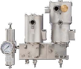
To ensure reliable performance, a high-integrity ESD package integrates several vital hardware layers:
- The Primary Valve: Typically a high-performance ball, gate, or triple offset butterfly valve.
- The Actuator: A heavy-duty, spring-return pneumatic or hydraulic cylinder.
- The Solenoid Valve: The electro-pneumatic trigger linked directly to the safety logic solver.
- Air Preparation Array: Dedicated filtration assemblies to safeguard incoming pneumatic supply.
- Position Instrumentation: Smart limit switches or transmitters to track exact stroke locations.
Because the final element contributes up to 50% of the total probability of failure on demand inside a safety loop, this assembly requires strict engineering focus.
The Anatomy of a Safety Instrumented Function (SIF)
An ESD valve operates as the final execution arm of a Safety Instrumented Function (SIF). The entire SIF behaves like a human body: pressure, temperature, or flow sensors act as the eyes to detect risks; the central logic solver acts as the brain; and the ESD valve assembly acts as the muscle to physically secure the process. If the muscle locks or responds too slowly, the entire automated safety loop fails to protect the asset.
Seven Critical Design Steps for High-Integrity ESD Systems
Step 1: Define Your Target Functional Safety Requirements
Reliable design starts by evaluating required Safety Integrity Levels (SIL 1, SIL 2, or SIL 3) based on IEC 61508 and IEC 61511 standards. Sourcing certified parts is not enough. Designers must calculate the total Average Probability of Failure on Demand ($\text{PFD}_{\text{avg}}$) across the entire loop, accounting for test intervals and required process response times.
Step 2: Calculate Conservative Actuator Safety Factors
Actuators must overcome a valve’s maximum breakaway torque, running friction, and seating loads under full differential pressure. Additionally, internal components age, and process deposits build up over time. Therefore, sizing formulas must apply generous safety factors (typically 1.5x to 2.0x minimum) to prevent the valve stem from sticking during a critical emergency shutdown.
Step 3: Optimize the Solenoid Valve Interface
The solenoid valve bridges the electronic safety system and the pneumatic actuator. Because solenoids contain small orifices and rely on internal seals, they are highly vulnerable to air contamination and coil burnouts. Project teams should select explosion-proof, corrosion-resistant solenoids with high exhaust flow capacities to ensure rapid actuator venting.
Step 4: Select a Proper Solenoid Redundancy Architecture
To balance safety reliability with plant availability, engineers deploy distinct voting arrangements:
- 1oo2 (One-out-of-Two): Either channel can trigger a shutdown. This setup maximizes safety but increases spurious trip risks.
- 2oo2 (Two-out-of-Two): Both solenoids must trip to execute a shutdown. This minimizes plant trips but introduces a single point of failure.
- 2oo3 (Two-out-of-Three): Merges the benefits of both architectures. The loop maintains full safety integrity while allowing on-line testing without causing a nuisance shutdown.
Step 5: Enforce Stringent Instrument Air Quality Limits
Contaminated pneumatic supply lines rapidly compromise ESD loops. According to ISO 8573 standards, instrument air must remain dry and completely free of oil or solid debris. Moisture carryover corrodes actuator cylinders and jams delicate solenoid spools, directly causing delayed emergency responses.
Step 6: Insulate Against Harsh Environmental Realities
Long-term field reliability depends entirely on environmental protection. ESD packages deployed in offshore atmospheres or aggressive chemical facilities require specialized construction. Using 316 stainless steel enclosures, custom offshore coatings, and robust UV-resistant seals ensures internal mechanical parts do not seize up in severe environments.
Step 7: Implement Online Partial Stroke Testing (PST)
Functional safety math assumes plants run periodic checks to catch hidden faults. Partial Stroke Testing (PST) provides a vital diagnostic layer by stroking the ESD valve slightly (typically 10% to 15%) without interrupting online production. This minor test uncovers seat stiction and spring fatigue early, lowering the loop’s overall $\text{PFD}_{\text{avg}}$ profile.
Why Shutdown Valves Fail in Real-World Scenarios
The overview below outlines the most frequent hidden failure mechanisms encountered by plant operators.
| Failure Mode | Hidden Mechanism | Engineering Remedy |
|---|---|---|
| Undersized Actuator | Calculated without accounting for seal aging or scale deposits. | Enforce a minimum 1.5x breakaway torque safety factor. |
| Severe Valve Stiction | Packing material dries out or deforms after sitting idle. | Deploy live-loaded packing and run automated weekly PSTs. |
| Solenoid Freeze-Up | Internal condensation mixes with ambient dust inside exhaust ports. | Install stainless steel bug screens on all exhaust vents. |
| Pneumatic Exhaust Lag | Long air lines or small ports restrict swift air evacuation. | Mount high-flow Quick Exhaust Valves (QEV) directly to the actuator. |
Frequently Asked Questions
What is the primary difference between a control valve and an ESD valve?
Control valves continuously modulate flow to manage process variables. Conversely, an ESD valve operates strictly on a binary basis—fully open or fully closed—and acts exclusively during emergency scenarios to secure a safe plant state.
Can an online process trip occur during a Partial Stroke Test (PST)?
Modern smart PST positioners limit valve travel electronically or mechanically. This failsafe mechanism ensures the valve can never overshoot its target testing window, keeping production completely stable.
Why are spring-return pneumatic actuators preferred over double-acting models for ESD lines?
Spring-return actuators offer mechanical fail-safe reliability. If instrument air supply pressure is lost entirely, the internal compressed springs mechanically drive the valve to its safe position without needing external power.
Key Takeaway for Safety Engineers
Designing an emergency shutdown system goes far beyond simply buying SIL-rated components. True loop safety demands careful attention to actuator torque safety margins, clean air distribution, robust solenoid voting logic, and online partial stroke testing. Treating the ESD package as a cohesive, single system ensures the valve will respond instantly when an emergency demand arises.